
PowerGuard-A 380/30 VDC 3 kW Marine Power Supply — Shipboard 3-Phase 380 VAC to 2 × 30 VDC
Model
PowerGuard-A 380/30
Input
3-phase 4-wire 380 VAC (Y, 220 VAC line-to-neutral), 50 / 60 Hz, ±15 %
Output
30 VDC nominal, adjustable 28–32 VDC via RS-485
Outputs
2 independent outputs (A / B), 50 A each, individually switchable and protected
Power
3.0 kW continuous · 3.5 kW peak (10 s), up to +45 °C ambient
Power factor
≥ 0.95 at full load, active PFC
Regulation / ripple
±1 % · ≤ 0.5 Vp-p (20 MHz bandwidth)
Isolation
Input–output 3 kVAC
Control
Isolated RS-485 Modbus RTU · remote ON/OFF per output · summary alarm relay
Cooling
Fanless, sealed, conduction-cooled (optional external fan kit)
Company:ITAR-FreeNCAGE: TM885
Overview
Product and Purpose
The PowerGuard-A 380/30 VDC Marine Power Supply converts the shipboard 3-phase 380 VAC supply into a regulated 30 VDC bus (adjustable 28–32 VDC) and distributes it to two independently protected, remotely switchable outputs of 50 A each. It delivers 3.0 kW continuous and 3.5 kW peak power from a sealed, fanless enclosure that mounts on a deck or bulkhead.
The unit is built on three industry-proven power stages certified to IEC/EN 62368-1, one per phase in a balanced star configuration, running in parallel with active current sharing. The TEDEG control and distribution board adds monitoring, protection and the customer interface: an isolated RS-485 Modbus RTU port, a remote ON/OFF contact for each output and a summary alarm relay. The unit is designed and manufactured by TEDEG in Ankara.
This page reflects the preliminary datasheet Rev. P2 (10/2026), prepared for project discussions: values are confirmed in the final technical proposal, and the temperature ratings will be confirmed by thermal testing. The images are concept visualisations; the final product may differ in detail.
Engineering Capability
Input:
| Feature | Value |
|---|---|
| Input | 3-phase 4-wire, 380 VAC (Y, 220 VAC line-to-neutral), 50 / 60 Hz |
| Operating range | 380 VAC ±15 % (line-to-neutral 187–253 VAC) |
| Power factor | ≥ 0.95 at full load, active PFC on each power stage |
| Phase loading | Balanced: one power stage per phase |
| Input protection | 3-pole input circuit breaker, EMI filter, surge protection, phase-loss monitoring |
Output:
| Feature | Value |
|---|---|
| Output voltage | 30 VDC nominal, adjustable 28–32 VDC (set via RS-485, retained in non-volatile memory) |
| Outputs | 2 independent outputs (A / B), each individually switchable and protected |
| Output current | 50 A per output (1.5 kW at 30 VDC) |
| Continuous power | 3.0 kW total up to +45 °C ambient, fanless |
| Peak power | 3.5 kW total, 10 s, up to +45 °C ambient |
| Voltage tolerance | ±1 % (set-up tolerance, line and load regulation) |
| Ripple and noise | ≤ 0.5 Vp-p (20 MHz bandwidth) |
| Redundancy | With one power stage out of service the unit continues at reduced power (≥ 2.5 kW at +45 °C) |
| Isolation | Input–output 3 kVAC |
Temperature rating (preliminary, to be confirmed by thermal test):
| Ambient | Standard — fanless, sealed | With optional external fan kit |
|---|---|---|
| 0 … +45 °C | 3.0 kW continuous · 3.5 kW peak | 3.0 kW continuous · 3.5 kW peak |
| +55 °C | 2.7 kW | 3.0 kW continuous · 3.5 kW peak |
| +65 °C | 1.7 kW | 3.0 kW continuous · 3.5 kW peak |
| +70 °C | 1.2 kW | 2.9 kW |
The external fan kit moves ambient air over the outside fins only; the electronics compartment stays sealed. A 4-stage version for 3.0 kW fanless up to +60 °C is available on request.
Protection:
| Protection | Description |
|---|---|
| Over-voltage | Independent hardware OVP on the control board (34 VDC), plus power-stage OVP |
| Over-current / short circuit | Electronic current limit and trip per output; power-stage constant-current limit |
| Over-temperature | Thermal shutdown with automatic recovery; temperatures reported via RS-485 |
| Input | Phase-loss and under-voltage detection with alarm |
| Reverse current | Blocking on each output |
Control and monitoring:
- RS-485: isolated, Modbus RTU (slave), 9.6–115.2 kbit/s, addressable
- Telemetry: input voltage per phase, output voltage, current and power per output, power-stage status and temperatures, operating hours, alarm and event log
- Commands: output A / B ON-OFF, output voltage set-point 28–32 VDC, alarm reset
- Remote ON/OFF: one dry-contact input per output in the SIGNAL & CONTROL connector (closed = ON), working together with the RS-485 commands
- Summary alarm: potential-free relay contact (COM, NO, NC)
- Indicators: five sealed 8 mm LED indicators: POWER, OUTPUT A and OUTPUT B (green), COMM (amber) and FAULT (red)
Connectors (preliminary):
| Interface | Connector |
|---|---|
| AC INPUT | MIL-DTL-38999 Series III receptacle, 4 power contacts + PE (L1, L2, L3, N, PE), with protective cap |
| OUTPUT A / OUTPUT B | High-current MIL-DTL-38999 Series III receptacle, 2-pole (+30 VDC, return), one per output, with protective cap |
| SIGNAL & CONTROL | MIL-DTL-38999 Series III receptacle: RS-485, remote ON/OFF A and B, summary alarm, spare contacts; with protective cap |
| Grounding | M6 chassis grounding stud on the front panel |
Mating plugs are supplied with the unit. Connector types and pin-outs can be adapted to the ship's installation standard; the full pin-out is given in the interface control document.
Mechanical and environmental:
| Feature | Value |
|---|---|
| Operating temperature | 0 … +70 °C (power per temperature table) |
| Storage temperature | −40 … +85 °C |
| Humidity | Up to 95 % RH, non-condensing; conformal-coated electronics |
| Cooling | Fanless: conduction to the finned enclosure walls and natural convection; optional external fan kit |
| Enclosure | Welded and machined marine-grade aluminium, sealed; RAL 7035 light grey powder coat over chromate conversion |
| Mounting | Two longitudinal rails with slotted holes below the cooling fins; deck or bulkhead mounting |
| Dimensions / weight | Body 316 × 506 × 256 mm; overall incl. fins and rails 376 × 596 × 298 mm (W × D × H); approx. 38 kg (preliminary) |
Typical Applications
- Shipboard installation: deck or bulkhead mounting on the two rails below the cooling fins
- Naval and marine platforms: 3-phase 380 VAC to 30 VDC conversion for onboard DC loads
- Mission equipment supply: two independently switchable and protected 50 A outputs
- Remote operation: control and monitoring from the ship's systems over RS-485 Modbus RTU
The TEDEG Advantage
Three line-replaceable power stages share the load, so the unit keeps running at reduced power (≥ 2.5 kW at +45 °C) if one stage is out of service. The output set-point is stored in the power stages: if the control board fails, the outputs stay at their set-point and the independent 34 VDC hardware over-voltage protection remains active. The sealed, fanless enclosure needs no filter cleaning or fan replacement.
The configuration can be adapted to the project: an external fan kit for full power up to +65 °C, a 4-stage version for 3.0 kW fanless up to +60 °C, a liquid-cooled version using the ship's fresh-water circuit, CAN bus or Ethernet (Modbus TCP) interfaces, and other output voltages in the 24–48 VDC range or more outputs. Every unit passes a 100 % factory test (functional, load and protection tests) with a test report, and a factory acceptance test (FAT) at TEDEG Ankara can be witnessed on request.
For 28 VDC from three-phase 380 VAC in vehicles and field systems, see the PowerGuard-A 380 VAC to 28 VDC converter; for the full range, browse AC-DC & DC-DC Power Converters.
Corporate assurance: TEDEG Defence is an approved supplier of ASELSAN, Roketsan and the Turkish Ministry of National Defence (MSB), with NATO supplier registration under NCAGE: TM885.
Specifications
| Model | PowerGuard-A 380/30 |
| Input | 3-phase 4-wire 380 VAC (Y, 220 VAC line-to-neutral), 50 / 60 Hz, ±15 % |
| Output | 30 VDC nominal, adjustable 28–32 VDC via RS-485 |
| Outputs | 2 independent outputs (A / B), 50 A each, individually switchable and protected |
| Power | 3.0 kW continuous · 3.5 kW peak (10 s), up to +45 °C ambient |
| Power factor | ≥ 0.95 at full load, active PFC |
| Regulation / ripple | ±1 % · ≤ 0.5 Vp-p (20 MHz bandwidth) |
| Isolation | Input–output 3 kVAC |
| Control | Isolated RS-485 Modbus RTU · remote ON/OFF per output · summary alarm relay |
| Cooling | Fanless, sealed, conduction-cooled (optional external fan kit) |
| Operating temperature | 0 … +70 °C (power per temperature table) · storage −40 … +85 °C |
| Dimensions / weight | 376 × 596 × 298 mm overall · approx. 38 kg (preliminary) |
| Data status | Preliminary datasheet Rev. P2 (10/2026) |
Datasheet
Related Products
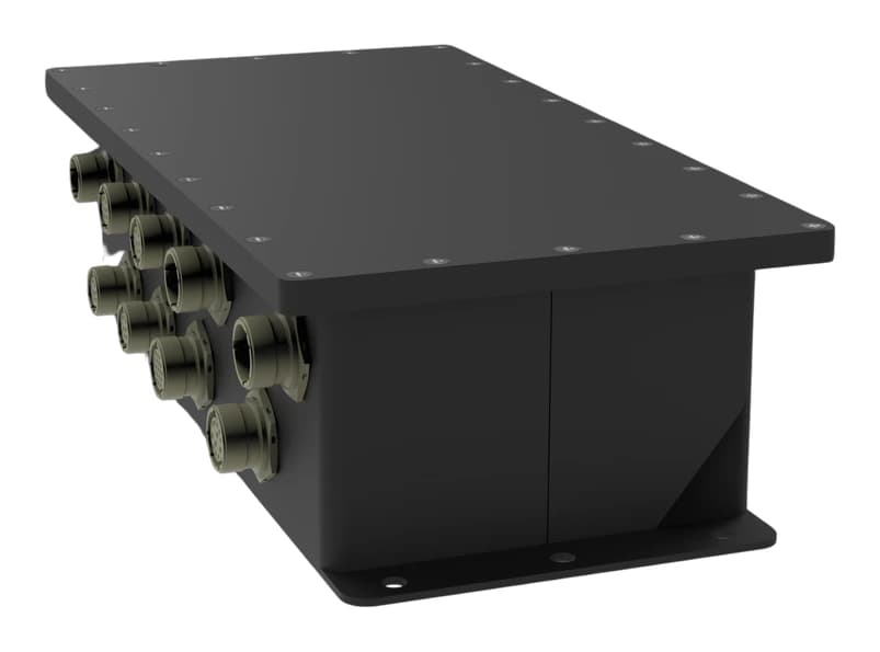
AC-DC & DC-DC Power Converters
PowerGuard-A 380 VAC to 28 VDC Military AC-DC Converter & Distribution System
Details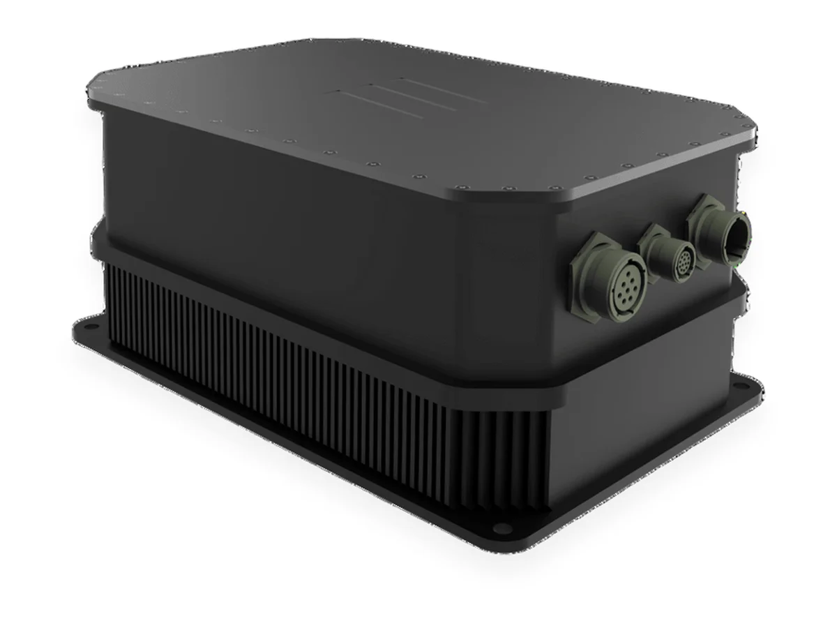
AC-DC & DC-DC Power Converters
Mil-Spec AC/DC Converter — Defense-Grade Power Supply
Details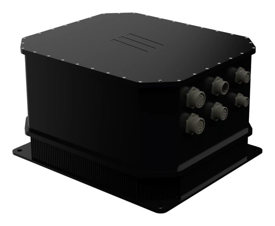
AC-DC & DC-DC Power Converters
PowerGuard TPS-28 Military Power Management Module (28 VDC Output)
DetailsFull category: mil-spec AC-DC and DC-DC converters
Engineering Support
Our engineering services can adapt this product to your platform, integrate it or test it against your programme requirements.
Quality and Testing
FAQ
What supply does it need, and what does it deliver?+
It takes a 3-phase 4-wire 380 VAC supply (Y, 220 VAC line-to-neutral, 50 / 60 Hz) within ±15 % and delivers 30 VDC nominal, adjustable between 28 and 32 VDC over RS-485. The power is split into two independent outputs, A and B, each rated 50 A (1.5 kW at 30 VDC). Total power is 3.0 kW continuous and 3.5 kW peak for 10 s, up to +45 °C ambient.
How much power is available at higher ambient temperatures?+
In the standard fanless, sealed configuration the preliminary rating is 3.0 kW up to +45 °C, 2.7 kW at +55 °C, 1.7 kW at +65 °C and 1.2 kW at +70 °C. With the optional external fan kit, which moves ambient air over the outside fins only, full power (3.0 kW continuous, 3.5 kW peak) is available up to +65 °C and 2.9 kW at +70 °C. A 4-stage version gives 3.0 kW fanless up to +60 °C. These values will be confirmed by thermal testing.
How is it controlled and monitored?+
Through an isolated RS-485 Modbus RTU port (slave, 9.6–115.2 kbit/s, addressable), which reports input voltage per phase, output voltage, current and power per output, power-stage status and temperatures, operating hours and an alarm and event log. Outputs A and B can be switched and the output voltage set-point adjusted over RS-485. The SIGNAL & CONTROL connector also carries a dry-contact remote ON/OFF input for each output and a potential-free summary alarm relay; five sealed LEDs on the front panel show the status.
What happens if a power stage or the control board fails?+
With one of the three power stages out of service the unit continues at reduced power, at least 2.5 kW at +45 °C. The output set-point is retained in the power stages, so if the control board fails the outputs stay at their set-point and the independent hardware over-voltage protection (34 VDC) remains active. The power stages and the control board are line-replaceable, and spare parts and technical support come from TEDEG.
Which connectors are used, and how is it mounted?+
The AC input, the two outputs and the SIGNAL & CONTROL interface use MIL-DTL-38999 Series III receptacles with protective caps; mating plugs are supplied, and connector types and pin-outs can be adapted to the ship's installation standard. The unit mounts on a deck or bulkhead using two longitudinal rails with slotted holes below the cooling fins. Overall dimensions are 376 × 596 × 298 mm (W × D × H) and the preliminary weight is about 38 kg.
Can the configuration be customised for my project?+
Yes. Options include an external fan kit, a 4-stage version, a liquid-cooled version using the ship's fresh-water circuit, CAN bus or Ethernet (Modbus TCP) interfaces, and other output voltages in the 24–48 VDC range or more outputs. Because this is a preliminary datasheet for project discussions, the final values are confirmed in the technical proposal; send your requirements through the quote form.