
Missile and Air Defence Radar Systems
Missile and Radar Systems — Military UPS and 400 Hz Converter Stable Down to a 0.3 Power Factor
For the low-power-factor radar and fire-control loads that make commercial UPS units and converters alarm and shut down, a domestic pair built around a control algorithm and power stage designed for capacitive load.
- Platform
- Missile fire-control unit and air surveillance radar — fixed and mobile sites
- Customer
- Leading Turkish Missile and Air Defence Radar Systems Integrator
- Sector
- Defence · missile / radar electronics
- Year
- 2025
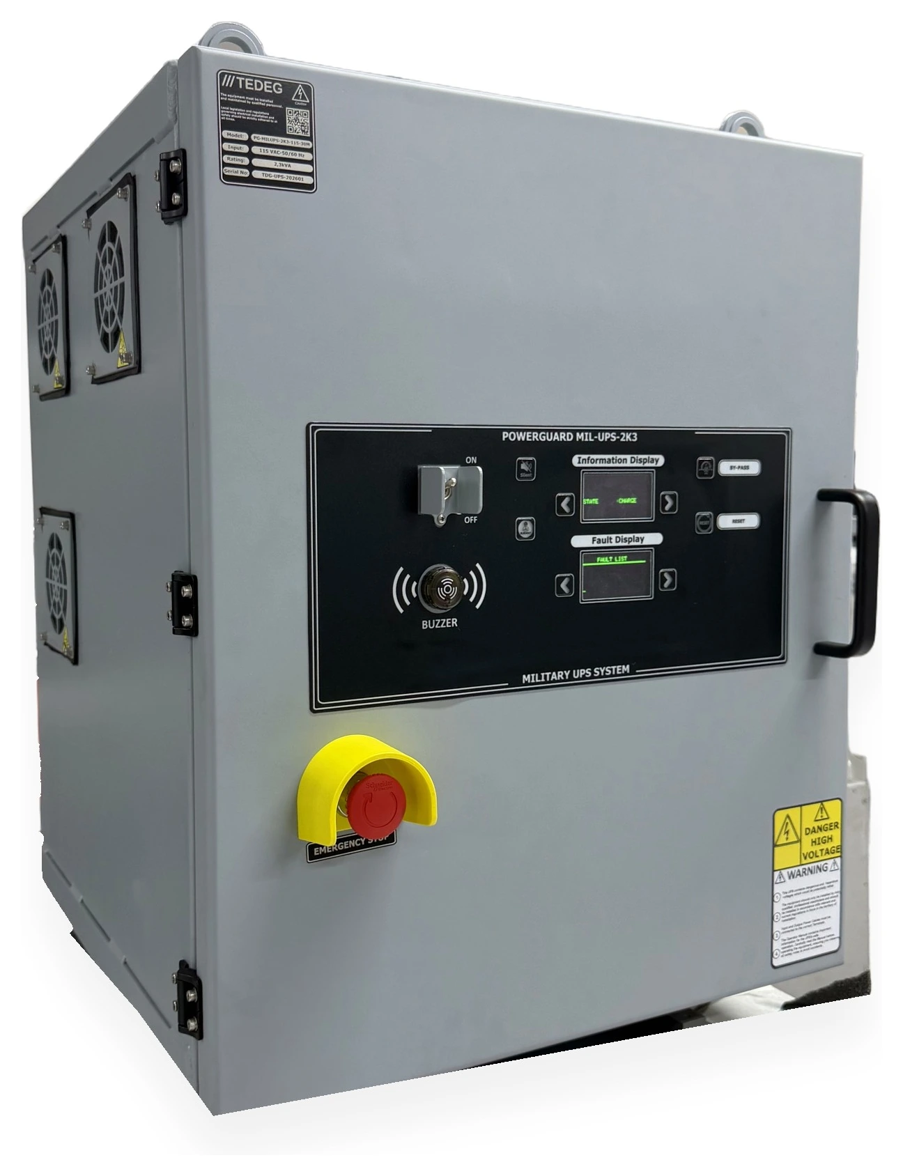
Customer & Context
A leading Turkish missile and air defence radar systems integrator approached TEDEG Defence while renewing the power infrastructure of its next-generation air surveillance radar and missile fire-control unit. In both systems the radar transceiver, fire-control electronics and signal processing units appear to the supply as a capacitive, low-power-factor load because of their switch-mode power supplies and filter capacitors. In standby and at low duty cycle the load power factor drops as far as 0.3.
The integrator had two needs: a UPS that keeps the 60 Hz transceiver and console loads running through a supply failure, and a static frequency converter that generates 400 Hz from the grid for the radar and fire-control subsystems that run on 400 Hz. Both units had to be designed to military standards, remain electromagnetically compatible alongside the radar transmitter, and stay stable on this load profile.
Challenge
Before procurement, the integrator had tested off-the-shelf products against its own load profile. The test reports and the technical requirements document handed to TEDEG pointed to these issues:
- Instability on capacitive load: commercial UPS units are designed around a power factor of about 0.8. On the radar transceiver's capacitive, low-power-factor load the inverter output voltage oscillated and the unit raised an overload alarm or dropped to bypass. Even with the load power below the kVA limit, the reactive current overstressed the inverter.
- The same picture on the converter side: industrial 400 Hz converters could not keep voltage and frequency modulation within limits on a capacitive load, and some shut their output down.
- Military requirements: none of the trial products was designed to MIL-STD-1399 input conditions, MIL-STD-810G shock and vibration or MIL-STD-461F EMI requirements; electromagnetic compatibility next to the radar transmitter was an open risk.
- Supply quality: a generator feeds the mobile site and a long grid line the fixed site; voltage fluctuation and harmonic distortion passed straight through to the load.
- Maintenance: there was no way to switch to bypass for testing and maintenance without dropping the load.
No UPS on the market was both military grade and stable down to a 0.3 power factor. The integrator started a development programme with TEDEG for a solution designed around this load profile.
TEDEG Solution
TEDEG Defence treated the two units around the same load profile: in the MIL-UPS-2K3 the inverter stage and control algorithm were designed specifically to feed a capacitive, low-power-factor load; on the 400 Hz side the PowerGuard static frequency converter was verified on the same test rig with the same radar load.
MIL-UPS-2K3 — Capacitive Load Down to a 0.3 Power Factor
Why a standard UPS becomes unstable on a capacitive load: the load current leads the voltage, interacts with the inverter output filter and voltage regulation breaks down. In the MIL-UPS-2K3 the control loop and output stage of the high-frequency PWM-controlled inverter were dimensioned for this reactive current, so the output stays a constant 115 VAC pure sine wave whether the load is capacitive, has a low power factor or draws inrush current. Rated 2.3 kVA with a nominal output of 750 W: that ratio shows the design is sized for reactive current rather than active power. Output is 60 Hz (±0.1 Hz) at 115 VAC ±2.5 VAC, regulation ±2%, THD below 3% on a linear load, transient response under 10 ms, and 20 A of inrush current is carried for 10 seconds. Capacitive loads are supported down to a 0.3 power factor.
AFE Input, Online Topology and 30 Minutes of Backup
In a double-conversion online topology the load is always fed through the inverter, so input interruptions, fluctuations and noise never reach it. The Active Front-End rectifier runs on a 3-phase 115 VAC ±20% (92–138 VAC), 45–65 Hz input with an input power factor above 0.95; sudden voltage changes, imbalances and harmonics from the generator or grid are isolated at the AFE stage. When the supply fails completely, the VRLA gel battery provides 30 minutes of backup. Manual bypass keeps the load on during maintenance and testing; dual OLED displays show information and the FAULT LIST, monitoring and remote on/off run over Ethernet (KN6), and BIT monitors status continuously. The design is based on MIL-STD-1399, MIL-STD-810G and MIL-STD-461F; the 5754 aluminium enclosure sits on 6-point vibration isolators and weighs 82 kg without batteries.
PowerGuard 400 Hz Static Frequency Converter — Radar and Fire-Control Supply
For the radar and fire-control subsystems that run on 400 Hz, a variable 115–220 VAC, 60–400 Hz output is produced from the 3-phase 360–440 VAC, 50–60 Hz supply; the 400 Hz output is taken as 115 VAC line-to-neutral in star connection or 115 VAC line-to-line in delta connection. Conversion is entirely static, with no rotating machine. Output THD is below 5%, frequency modulation at most 4 Hz and voltage modulation at most 2.5 Vrms; the system reaches steady state within 200 ms and shuts the output down within 100–170 ms on over- or under-voltage. The converter was verified on the same test rig with the integrator’s radar load profile. BIT, OLED, RS-422 and the Ethernet-based desktop software list per-phase currents and voltages, unbalanced load and temperature alerts. Output requirements to MIL-STD-1399B and MIL-STD-1399-300B, environmental resistance to MIL-STD-810G; −30 °C … +50 °C, 3000 m altitude.
Outcome
The verification unit was trialled on the integrator's test infrastructure with the radar transceiver and a capacitive load bank; series production qualification is under way.
- A constant 115 VAC pure sine wave on capacitive load down to a 0.3 power factor; the alarms and drops to bypass seen with the trial products did not recur.
- Generator and grid disturbances stayed at the AFE stage; with 30 minutes of backup, radar and console remain up through a supply failure.
- The 60 Hz and 400 Hz loads are fed by two matched products from a single supplier, with electromagnetic compatibility addressed in the design.
- Maintenance and testing are carried out on manual bypass without dropping the load.
The integrator has adopted the same power architecture as the basis for its next radar sites.
Technical Scope
Values are taken from each product's own technical data; full specifications are on the product page.
- Topology
- Double-conversion online · AFE input
- Input
- 115 VAC ±20%, 45–65 Hz, 3-phase
- Output
- 115 VAC ±2.5 VAC, 60 Hz, pure sine
- Rating
- 2.3 kVA (750 W nominal · 2.3 kW max.)
- Backup
- 30 min · VRLA gel battery
- Load power factor
- Capacitive loads down to 0.3
StandardsMIL-STD-1399MIL-STD-810GMIL-STD-461FView product: PowerGuard MIL-UPS-2K3 Mil-Spec Military UPS System- Input
- 3-phase, 360–440 VAC, 50–60 Hz
- Output
- Variable 115–220 VAC, 60–400 Hz
- Connection
- Star 115 VAC (L-N) · Delta 115 VAC (L-L), 400 Hz
- Efficiency
- At least 85%
- THD
- Below 5%
- Frequency modulation
- Max. 4 Hz
StandardsMIL-STD-810GMIL-STD-461GMIL-STD-1399BView product: PowerGuard 115/200 VAC 400 Hz Military Static Frequency Converter
More case studies
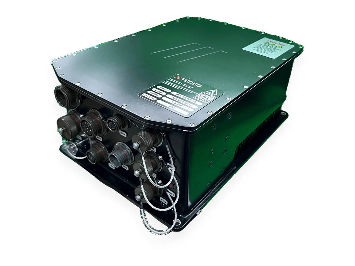
Air Defence · 2025
Mobile Air Defence Platform — Pedestal Motor Control & Radar Frequency Feed
A motor drive and a frequency converter sourced from separate foreign suppliers were replaced by a matched TEDEG pair, designed together so that neither interferes with the other.
Read case study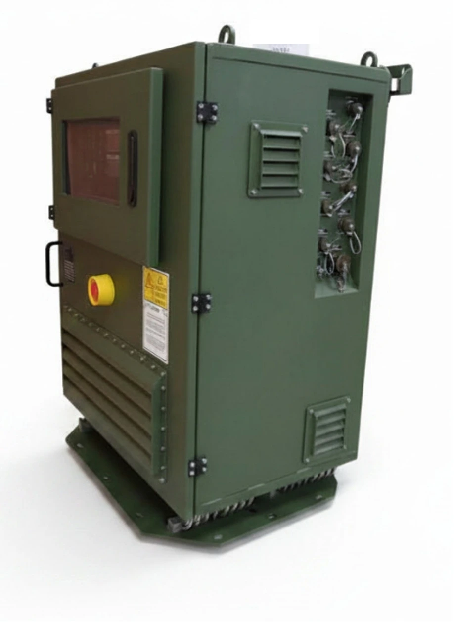
Land — Rocket / Missile Platforms · 2025
Land Rocket Platform — From Three Separate Systems to One Integrated Solution
The outdoor-rated military 60 Hz and 400 Hz solution the manufacturer could not find on the market: a single PowerGuard Outdoor replaced three systems combined in an industrial enclosure.
Read case study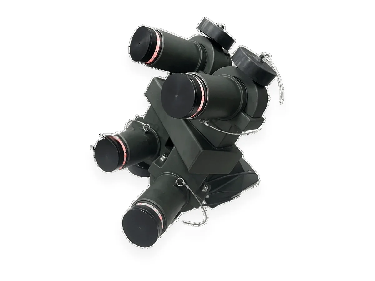
Land Platforms · 2025
Armoured Vehicle Family — One Smoke Launcher Architecture, 4 to 16 Launchers
Instead of a separate imported smoke system for every vehicle variant, one domestic system whose launcher count and coverage are chosen per variant and which joins the vehicle data bus over J1939.
Read case study