
PowerGuard TPS-115 115 VAC / 400 Hz Converter System — 3-Phase 400 Hz AC + 28 VDC
Part number (P/N)
TDG-PFC-A0001
Input
200–240 VAC, 50 Hz
AC output
3-phase 115 VAC L–N, 400 Hz, 600 VA
DC outputs
3 × isolated 28 VDC, 600 W total
Topology
AFE (Active Front End)
Communication
RS-485 HD, 10 Mbps
BIT
Automatic self-test twice per second
Cooling
Passive (fanless), optional thermostatic fan
Operating temperature
-40 °C to +55 °C
Dimensions
215 × 340 × 123 mm
Company:ITAR-FreeNCAGE: TM885
Overview
Product and Purpose
The PowerGuard TPS-115 — 115 VAC / 400 Hz Converter System is built to meet the 400 Hz AC and 28 VDC supply needs of military platforms in a single compact unit. It converts 230 VAC grid power into a 3-phase 115 VAC L–N, 400 Hz AC output and, in addition, provides 28 VDC outputs through isolated AC/DC converters.
All AC and DC outputs are individually switchable, with current and voltage measured and monitored in real time. An MCU-based smart control unit and an RS-485 interface allow the system to be monitored, controlled and diagnosed remotely.
Engineering Capability
Power architecture:
| Module | Output | Power | Feature |
|---|---|---|---|
| Module 1 — isolated AC/AC converter | 3-phase 115 VAC L–N, 400 Hz | 600 VA | Per-phase V/I measurement and ON/OFF |
| Module 2 — isolated DC/DC converter | 2 × 28 VDC | 300 W | Switchable, independent V/I measurement |
| Module 3 — isolated DC/DC converter | 1 × 28 VDC | 300 W | Switchable, V/I measurement |
- Input: 200–240 VAC, 50 Hz; input protection against overvoltage and surges
- AFE (Active Front End) topology: High power factor, low harmonic distortion, minimal impact on the grid
- Total DC output power: 600 W; ripple and noise max. 150 mVp-p
- Isolation: Every power converter and every output module independently isolated
- Connections: Industrial terminal blocks for input and outputs
Control, monitoring and diagnostics:
- Control: MCU-based smart control board; separate remote ON/OFF for every AC phase and every DC output
- Communication: 1 × RS-485 HD, 10 Mbps; real-time current/voltage, status and fault data
- Status outputs: Open-drain outputs for voltage status and system health
- BIT (Built-In Test): Automatic self-test twice per second with fault reporting
- Fault diagnosis: Approximately 90% accuracy with a JIT (Just-In-Time) approach
- Protection: Overvoltage (OVP), overcurrent / overload (OCP / OLP), overtemperature (OTP)
Mechanical and environmental:
| Feature | Value |
|---|---|
| Dimensions (W × H × D) | 215 × 340 × 123 mm |
| Enclosure | Finned aluminium body, perforated top cover |
| Mounting | 4-point mounting via base flanges |
| Cooling | Passive (fanless); temperature-activated fan optional |
| Operating temperature | −40 °C … +55 °C |
Typical Applications
- Military land platforms: 115 VAC / 400 Hz and 28 VDC supply for command, control and mission electronics
- Mobile mission systems: Field-deployed radar, communication and sensor systems
- Command and control centres: Monitored power for mission-critical equipment
- Test and validation systems: Power electronics and military electronics testing
- Naval platforms: Mission electronics and auxiliary systems on ships and boats
- Forward bases and field operations: Passively cooled, remotely monitored power in harsh conditions
Land and Naval Mission Electronics
TPS-115 is sized for mission electronics that need a 400 Hz AC supply and 28 VDC at the same time, on land platforms as well as on ships and boats. Typical integrations:
- Land vehicles and field-deployed systems: command, control and mission electronics, and field-deployed radar, communication and sensor systems, supplied with 3-phase 115 VAC L–N, 400 Hz (600 VA) and three isolated 28 VDC outputs (600 W total) from one 215 × 340 × 123 mm unit with 4-point base-flange mounting
- Ships and boats: mission electronics and auxiliary systems fed from a 200–240 VAC, 50 Hz supply, with every AC phase and every 28 VDC output switched remotely
- Test and integration benches: powering 400 Hz and 28 VDC military electronics during test and validation, with voltage and current read on every output
For the platform's mission computer or monitoring system, TPS-115 reports real-time current, voltage, status and fault data over RS-485 HD (10 Mbps), and its open-drain status outputs give a hardwired voltage-status and system-health signal. BIT runs automatically twice per second, and fault diagnosis with the JIT approach is approximately 90% accurate. Passive, fanless cooling (a temperature-activated fan is optional) supports operation from −40 °C to +55 °C.
The TEDEG Advantage
On most platforms, 400 Hz power and 28 VDC power come from two separate devices. TPS-115 combines both in a single compact 215 × 340 × 123 mm enclosure and makes every output individually monitored and switchable. For higher power or outdoor use, the PowerGuard Outdoor 60/400 Hz Frequency Converter and the 115/200 VAC 400 Hz Static Frequency Converter are in the same family.
Corporate assurance: TEDEG Defence is an approved supplier of ASELSAN, Roketsan and the Turkish Ministry of National Defence (MSB), with NATO supplier registration under NCAGE: TM885.
Images: The images on this page are representative (3D model).
Specifications
| Part number (P/N) | TDG-PFC-A0001 |
| Input | 200–240 VAC, 50 Hz |
| AC output | 3-phase 115 VAC L–N, 400 Hz, 600 VA |
| DC outputs | 3 × isolated 28 VDC, 600 W total |
| Topology | AFE (Active Front End) |
| Communication | RS-485 HD, 10 Mbps |
| BIT | Automatic self-test twice per second |
| Cooling | Passive (fanless), optional thermostatic fan |
| Operating temperature | -40 °C to +55 °C |
| Dimensions | 215 × 340 × 123 mm |
| Power | 600 VA (AC) + 600 W (DC) |
Datasheet
Related Products
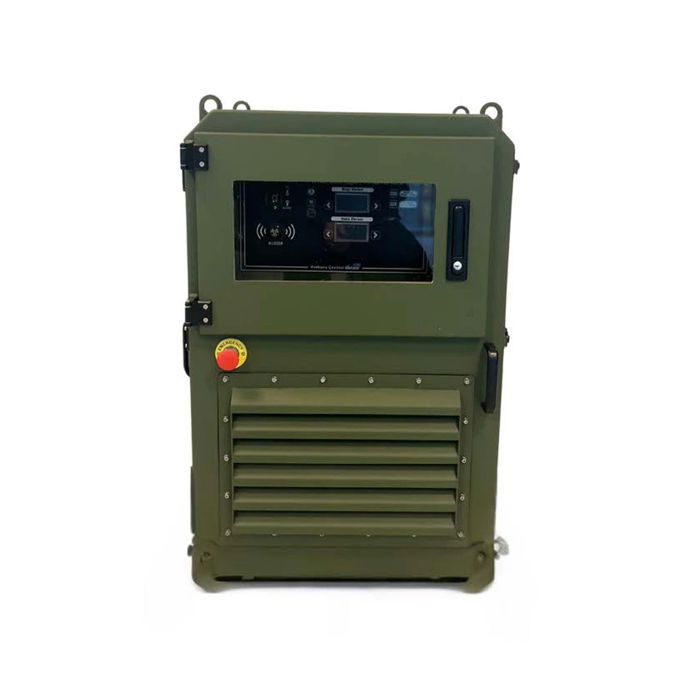
Frequency Converters, Motor Drives & Military UPS Systems
PowerGuard 115/200 VAC 400 Hz Military Static Frequency Converter
Details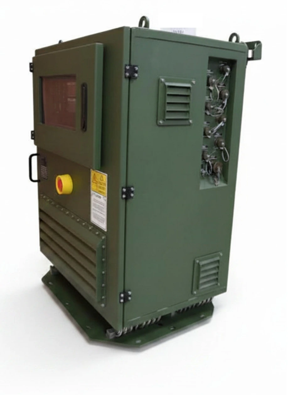
Frequency Converters, Motor Drives & Military UPS Systems
PowerGuard Outdoor 115 VAC 60/400 Hz Military Mobile Frequency Converter
Details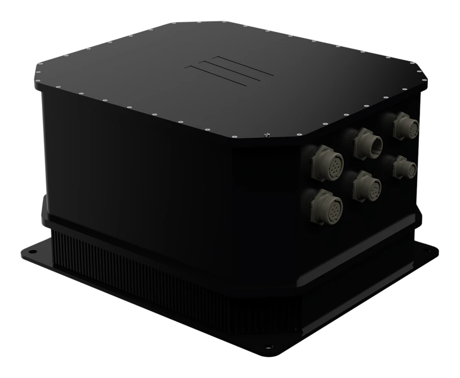
AC-DC & DC-DC Power Converters
PowerGuard TPS-28 Military Power Management Module (28 VDC Output)
DetailsFull category: military frequency converters and 400 Hz power systems
Engineering Support
Our engineering services can adapt this product to your platform, integrate it or test it against your programme requirements.
Quality and Testing
Related Guides
FAQ
What outputs does TPS-115 provide?+
A single unit provides a 3-phase 115 VAC L–N, 400 Hz, 600 VA AC output and three isolated 28 VDC outputs (600 W total). Two of the 28 VDC outputs come from one 300 W module and the third from a separate 300 W module.
What input does it run from?+
It runs from a 200–240 VAC, 50 Hz grid input, with input protection against overvoltage and surges. Its AFE topology keeps harmonic feedback to the grid low.
Can the outputs be controlled individually?+
Yes. There is separate remote ON/OFF control for every AC phase and every 28 VDC output. Voltage and current of all converters and output switches can be read over RS-485.
How are faults detected?+
Built-in test (BIT) runs automatically twice per second and reports faults to the user. Fault diagnosis accuracy with the JIT approach is approximately 90%. Open-drain status outputs report voltage status and system health.
What are the cooling and operating temperature?+
The standard design is passively cooled and fanless; the finned aluminium body dissipates heat. A temperature-activated fan is optional depending on operating conditions. Operating temperature is −40 °C … +55 °C.
Is TPS-115 suitable for land vehicle and naval mission electronics?+
Yes. Its datasheet lists military land platforms (command, control and mission electronics), mobile radar, communication and sensor systems, and mission electronics on ships and boats among its typical applications. One unit supplies 3-phase 115 VAC 400 Hz (600 VA) and three isolated 28 VDC outputs (600 W total) from 200–240 VAC, 50 Hz, and every output is monitored and switched over RS-485. Platform-specific environmental and EMC requirements are reviewed at project stage.