
Naval Systems
Naval Platform — Isolated 115 VAC for Mission Equipment from a 400 VAC Ship Supply
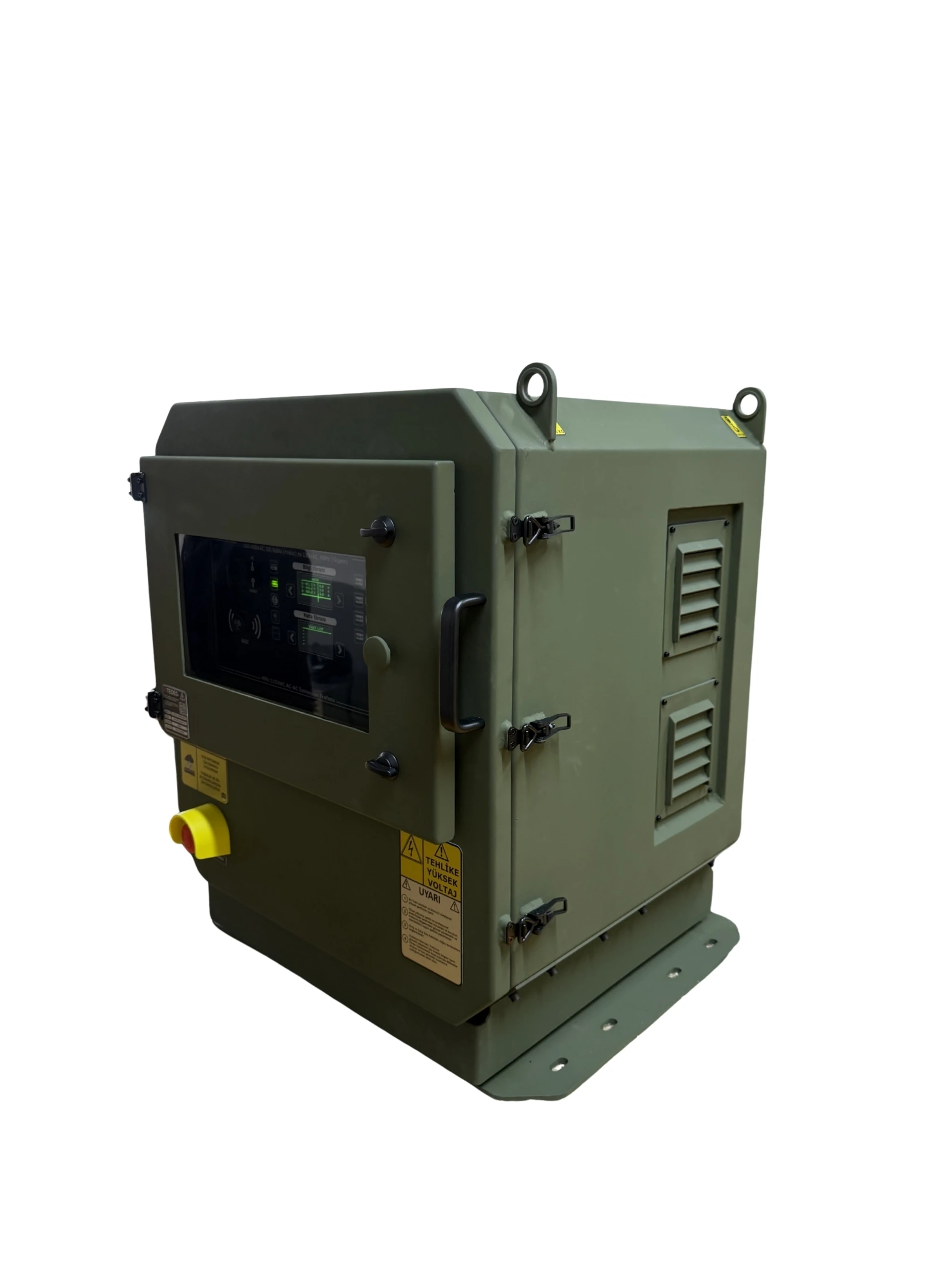
For a surface platform programme that had to connect 115 VAC mission equipment to a 3-phase 400 VAC ship supply, a 10 kVA converter with an isolated output transformer that manages four load groups separately: the PowerGuard 400/115 VAC AC-AC Military Inverter.
- Platform
- Surface platform — 3-phase 400 VAC ship supply, four groups of mission equipment running on 115 VAC
- Customer
- Leading Turkish Naval Platform Systems Integrator
- Sector
- Naval · surface platforms
- Year
- 2025
Customer & Context
A leading Turkish naval platform systems integrator approached TEDEG Defence for the mission equipment supply of a surface platform programme. The platform's distribution supply was 3-phase 400 VAC, while part of the mission equipment selected for the programme had been built for a 115 VAC supply and could not be connected to it directly. Because the equipment accepted 50 Hz, what was needed was not frequency conversion but voltage conversion and isolation.
The integrator sent TEDEG its electrical interface requirements and load list. The loads fell into four groups: two needed 3-phase and two needed 2-phase 115 VAC. The request was for a single converter that was MIL-STD-1399B compliant, delivered its output through an isolating transformer, could switch the four load groups individually and could be monitored over Ethernet from the command position. The commercial transformer solutions evaluated earlier did not meet the platform's isolation, EMI and shock and vibration requirements together.
Challenge
The assessment by the integrator's electrical design team listed where a solution built on commercial transformers fell short:
- Voltage mismatch: 115 VAC mission equipment could not be connected directly to the 400 VAC ship supply, and a separate transformer for each equipment group added both space and cabling.
- Isolation and EMI: commercial transformers could not document the required insulation between the ship supply and sensitive mission electronics, and meeting the military EMI/EMC requirement called for extra filtering and cabinet design.
- Shock and vibration: industrial cabinets and terminal-block connections were not designed for the platform's shock, vibration and humidity conditions, and the connections were not military connectors.
- Managing load groups: a transformer gave a single output; switching four equipment groups individually meant adding a separate distribution and switching stage.
- No remote monitoring: phase voltages and currents could only be measured at the device; there was no way to see the status from the command position or to cut the outputs in an emergency.
- Peak loads: during the short peaks that occur when equipment starts, protective devices tripped and the supply was lost.
The integrator decided to have TEDEG build a military converter that would cover all of these requirements in one cabinet.
TEDEG Solution
TEDEG Defence brought the integrator's requirements together in the PowerGuard 400/115 VAC AC-AC Military Inverter (TDG-PFC-A0115): 115 VAC, 50 Hz from a 3-phase 400 VAC input through an isolating transformer, with a total of 10 kVA on four separate outputs, each with its own military connector and its own button. The load groups were allocated to these four outputs according to the integrator's load list.
10 kVA Across Four Outputs, Isolated Output Transformer
The converter takes the 3-phase 400 VAC, 50/60 Hz ship supply (R, S, T and neutral) on input KN1 and delivers every output at 115 VAC, 50 Hz. The "400" in the name refers to the input voltage; the unit does not produce 400 Hz. Total power is 10 kVA continuous at 0.8 power factor, split across four outputs: KN2 at 3.6 kVA and KN3 at 2.4 kVA as 3-phase, KN4 and KN5 at 2 kVA each as 2-phase 115 VAC outputs. The outputs are delivered through an isolated output transformer, which provides high-voltage insulation between the ship supply and the mission equipment. The input uses a MIL-DTL-5015 series connector and the outputs MIL-DTL-38999 series military connectors; because each load group has its own connector, the harnesses stay separate. Efficiency is at least 85%.
Monitoring and Control from the Command Position
The Ethernet interface on KN6 allows the unit to be monitored and switched on and off remotely. The desktop remote control and monitoring software shows the input phase voltages (R, S, T) and phase currents together with the voltage and current of each output; commands to the output units, including the emergency command, are sent from the same software. On the unit itself there is Built-In Test (BIT) status monitoring, an OLED information and fault display and a separate colour-coded button for each output, so an operator can also switch one load group at the unit without touching the others.
Overload Headroom and Environment
Under overload the converter withstands 125% for 5 minutes, 200% for 5 seconds and 250% for 1 second, so the short peaks that occur when equipment starts are carried without interrupting the supply. Overload, short-circuit and over-temperature protection are built in. The system is designed for indoor and outdoor use from −30 °C to +50 °C; its dust, vibration, humidity, rain and shock resistance is in line with MIL-STD-810G, and the system has passed MIL-STD-810G testing. The converter is also MIL-STD-1399B and MIL-STD-461G (EMI/EMC) compliant. It weighs 160 ± 5 kg. For equipment on the platform that needs 400 Hz power the static frequency converter from the same family is available, and for 400 VAC distribution the AC power distribution panel.
Outcome
The PowerGuard 400/115 was delivered to the integrator's surface platform programme, and the 115 VAC mission equipment was connected to the ship supply through a single converter.
- Four load groups are managed separately, each with its own connector and button.
- The isolated output transformer provides galvanic isolation between the 400 VAC ship supply and the 115 VAC mission equipment.
- Phase voltages and currents are monitored over Ethernet from the command position, and the emergency command is issued from the same software.
- Overload headroom of up to 250% keeps the supply running through short peak loads.
- One cabinet in place of separate transformers and an added switching stage, with MIL-STD-1399B, MIL-STD-810G and MIL-STD-461G compliance in a single product.
Technical Scope
Values are taken from each product's own technical data; full specifications are on the product page.
- Input
- 3-phase, 400 VAC, 50/60 Hz
- Output
- 115 VAC, 50 Hz
- Total power
- 10 kVA continuous at 0.8 PF
- Outputs
- 3.6 + 2.4 kVA (3-phase) · 2 + 2 kVA (2-phase)
- Overload
- 125% 5 min · 200% 5 s · 250% 1 s
- Efficiency
- At least 85%
StandardsMIL-STD-810GMIL-STD-1399BView product: PowerGuard 400/115 VAC AC-AC Military Inverter — 10 kVA, 4 Outputs- Input
- 3-phase, 360–440 VAC, 50–60 Hz
- Output
- Variable 115–220 VAC, 60–400 Hz
- Connection
- Star 115 VAC (L-N) · Delta 115 VAC (L-L), 400 Hz
- Efficiency
- At least 85%
- THD
- Below 5%
- Frequency modulation
- Max. 4 Hz
StandardsMIL-STD-810GMIL-STD-461GMIL-STD-1399BView product: PowerGuard 115/200 VAC 400 Hz Military Static Frequency Converter- Input voltage
- 400 VAC
- Output voltage
- 400 VAC / 230 VAC
- Remote on/off signal
- 28 VDC / 230 VAC
- Output protection
- Individual breaker per output
- Phase indicator lamps
- 3
- Operating temperature
- −32 °C to +50 °C
More case studies
Air Defence · 2025
Mobile Air Defence Platform — Pedestal Motor Control & Radar Frequency Feed
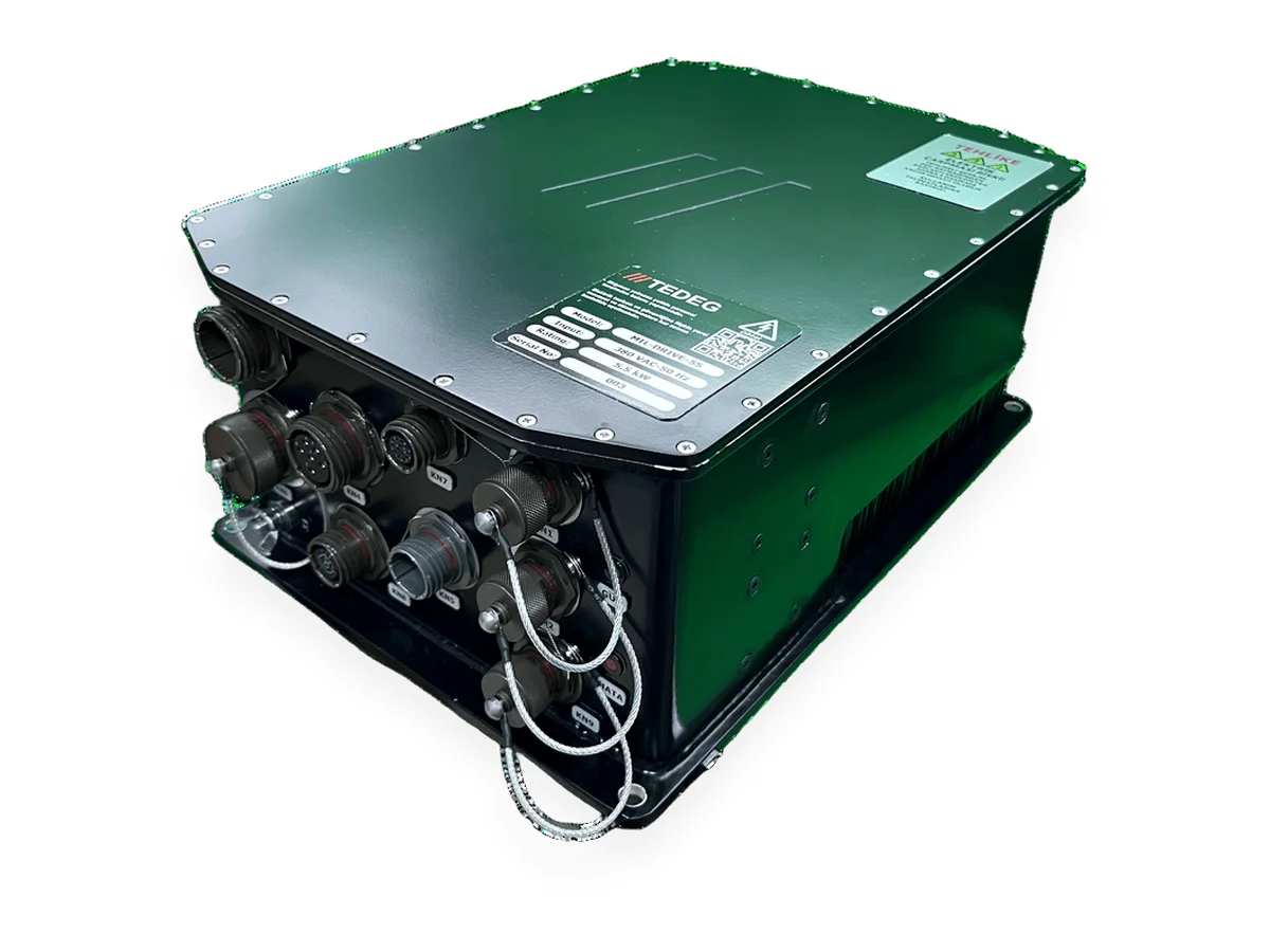
A motor drive and a frequency converter sourced from separate foreign suppliers were replaced by a matched TEDEG pair, designed together so that neither interferes with the other.
Read case study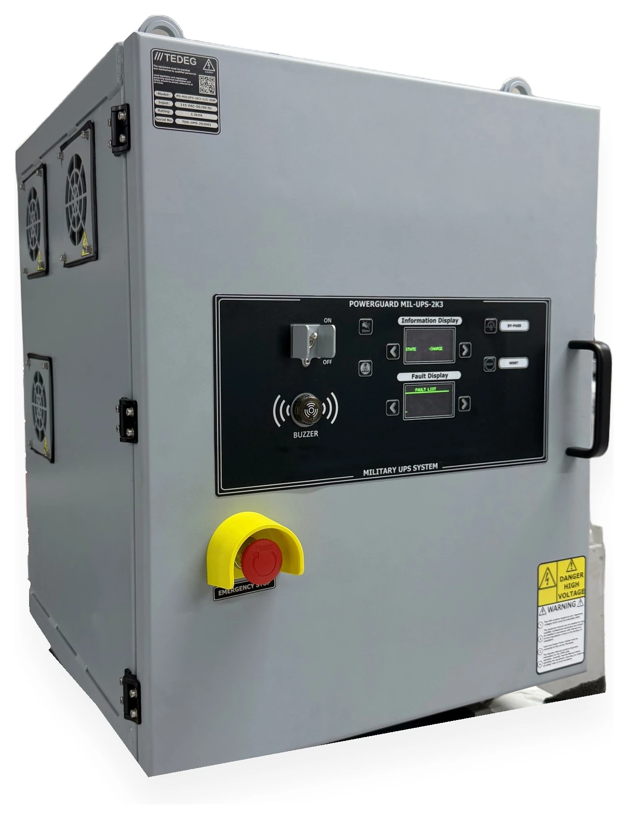
Missile and Air Defence Radar Systems · 2025
Missile and Radar Systems — Military UPS and 400 Hz Converter Stable Down to a 0.3 Power Factor
For the low-power-factor radar and fire-control loads that make commercial UPS units and converters alarm and shut down, a domestic pair built around a control algorithm and power stage designed for capacitive load.
Read case study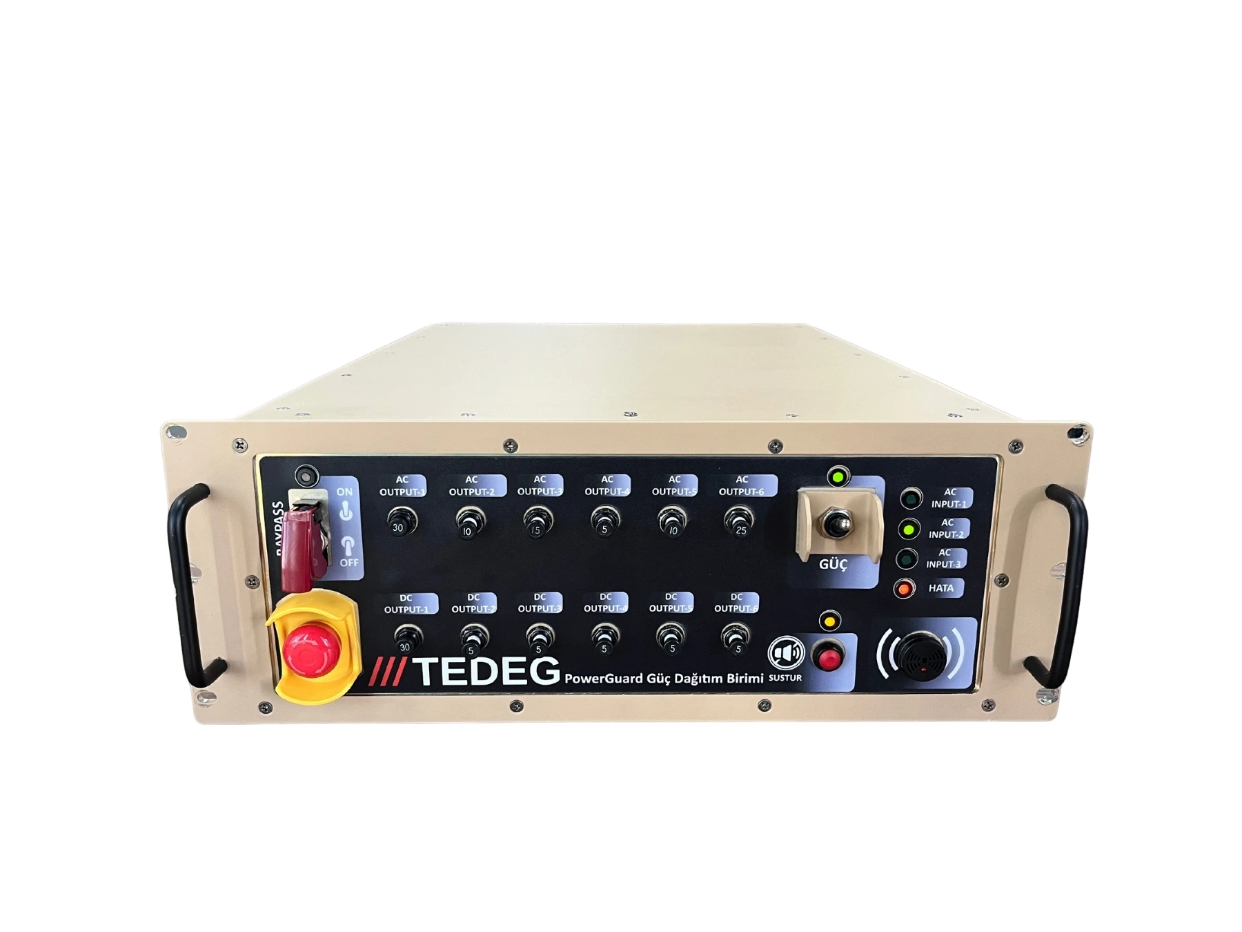
Land Platforms · 2024
Tactical Truck Power Architecture Modernisation
An ageing PDU that could no longer keep pace with growing mission loads was replaced by a remotely monitored power distribution architecture built on the PDU-RT5002 and designed to MIL-STD requirements.
Read case study