
Tactical Wheeled Vehicles
Tactical Vehicle 360° Camera Suite — From 11 Separate Power Supplies to One Power Module
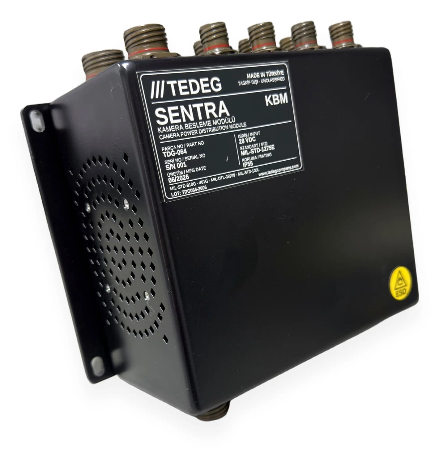
For a situational awareness suite that fed its cameras, mission computer, operator display and seat module from separate supplies, the SENTRA KBM camera power distribution module, built around the customer’s Technical Requirements Document and ICD.
- Platform
- 4×4 armoured tactical wheeled vehicle — 360° cameras, night-vision and driver-assistance cameras, mission computer, operator display, seat module
- Customer
- Leading Turkish Tactical Wheeled Vehicle Manufacturer
- Sector
- Defence · vehicle electronics (vetronics)
- Year
- 2026
Customer & Context
A leading Turkish tactical wheeled vehicle manufacturer approached TEDEG Defence while developing a new situational awareness suite for its 4×4 armoured vehicle family. The suite combined 360° surround cameras, night-vision and driver-assistance cameras, a mission computer, an operator display and a crew seat module.
On the first integration prototype, every camera was fed from its own power supply, and the mission computer and display had converters of their own. As the suite grew, so did the number of boxes, connectors and cables in the cabin. Before moving to series production, the manufacturer decided to simplify the architecture and sent TEDEG a Technical Requirements Document together with an Interface Control Document (ICD). The requirement was clear: a single module, fed from the vehicle's 28 VDC military bus, providing isolated camera outputs, also supplying the mission computer, display and seat module, and carrying the video lines in the same harness.
Challenge
Integration tests on the prototype vehicle and notes from the manufacturer's field trials made the drawbacks of the separately fed architecture plain:
- Harness size and failure points: every camera needed its own power supply, power cable and video cable. The harness volume in the cabin kept growing, and each new connection point became a potential failure point under vibration.
- Transients on the vehicle bus: transients from cranking, the alternator and load switching on the 28 VDC vehicle line passed straight through the commercial camera power supplies to the cameras, and some cameras showed image dropouts and restarts.
- Connector count: each camera used one power and one video connector, with audio and IR control lines routed separately. Assembly time and the risk of misconnection went up.
- Common ground and noise: because the supplies shared a common reference, ground-loop interference appeared on the video lines.
- Maintenance: when a camera failed in the field, it was hard to trace which supply fed which camera, and fault finding took longer.
- Military requirements: the commercial supplies in use were not designed to MIL-STD-1275E, MIL-STD-461G or MIL-STD-810G.
The manufacturer started a development and qualification programme with TEDEG for a solution that would meet all of these requirements in one module.
TEDEG Solution
TEDEG Defence brought the manufacturer's requirements together in the SENTRA KBM Camera Power Distribution Module: every supply line the suite needs is distributed from one compact unit over galvanically isolated outputs. Configuration, pin assignments and harness interfaces were finalised for the platform through the manufacturer's ICD.
From One Input to Isolated Outputs
The module is fed from the vehicle’s 28 VDC military electrical system through a MIL-STD-1275E compliant input with reverse polarity protection and galvanic isolation, and the power input connector carries a reverse polarity warning label. On the output side there are at least 11 camera outputs at 12 VDC, each one isolated. The mission computer is supplied at 24 VDC ±0.2 V with at least 200 W, and the operator display at an isolated 24 VDC ±0.2 V with at least 25 W; a separate isolated 24 VDC ±0.2 V output is reserved for the seat module. The isolated output architecture was chosen to keep transients on the vehicle bus and common-ground noise away from the cameras and the video lines.
One Connector per Camera, One Harness
Each camera connects to its own 5-pin D38999/24WA35PN connector, which carries video, audio and IR control lines together with the supply (V+, GND). Power and signal for each camera now share a single connector. At least 12 video lines at 75 Ω run through a single harness. The power input sits on a 4-pin D38999/24WC4SN and the computer interface on a 16-pin D38999/24WC35SN connector, while the display, computer and seat module outputs are grouped on the 18-pin D38999/24WD18PA power output connector. All connectors are from the MIL-DTL-38999 family, and pin assignments were defined for the platform through the ICD.
Mechanical Design and Environmental Requirements
The ≥ IP55 aluminium enclosure has a chromate coating; the module is secured to the vehicle with 4-point bolted mounting via the base flange, using A4-70 stainless steel fasteners. The identification plate is laser-marked to MIL-STD-130L and carries an ESD warning label. Operating and storage temperature is −32 °C … +55 °C; humidity, rain, sand-dust, salt fog, solar radiation, vibration and 20 g / 11 ms shock are specified under MIL-STD-810G CHG-1 methods. MIL-STD-461G (CE102, CS101/114/115/116, RE102, RS103) was the reference for EMI/EMC and MIL-STD-464C at system level. The product is COTS, with a service life of at least 30 years with periodic maintenance.
Outcome
The verification unit (S/N 001, manufactured 06/2026) has been delivered to the manufacturer; integration testing on the prototype vehicle and series production qualification are under way.
- The entire suite is supplied from one module: at least 11 isolated camera outputs, the mission computer, the operator display and the seat module.
- One MIL-DTL-38999 connector per camera instead of separate power and video connectors, with the video lines in the same harness.
- The MIL-STD-1275E input and galvanic isolation separate vehicle bus transients from the camera side.
- During maintenance, each camera's supply can be traced connector by connector on a single module.
- The COTS design allows fast procurement in series production.
Technical Scope
Values are taken from each product's own technical data; full specifications are on the product page.
- Input
- 28 VDC · MIL-STD-1275E
- Camera outputs
- Min. 11 × 12 VDC, isolated
- Computer output
- 24 VDC ±0.2 V · min. 200 W
- Display output
- 24 VDC ±0.2 V · isolated · min. 25 W
- Seat module output
- 24 VDC ±0.2 V · isolated
- Video lines
- Single harness · min. 12 × 75 Ω
StandardsMIL-STD-810GMIL-STD-461GMIL-STD-464CView product: SENTRA KBM Military Camera Power Distribution Module- Channels
- 32 (16 seats + 16 belts)
- Communication
- CAN-Bus · ISO 11898 · 500 kbps
- Supply
- 18–32 VDC (24 VDC nominal)
- Power consumption
- < 15 W
- Sensor architecture
- Chassis-referenced
- Ingress protection
- IP65
More case studies
Land Platforms · 2025
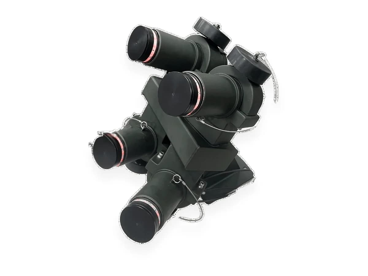
Armoured Vehicle Family — One Smoke Launcher Architecture, 4 to 16 Launchers
Instead of a separate imported smoke system for every vehicle variant, one domestic system whose launcher count and coverage are chosen per variant and which joins the vehicle data bus over J1939.
Read case study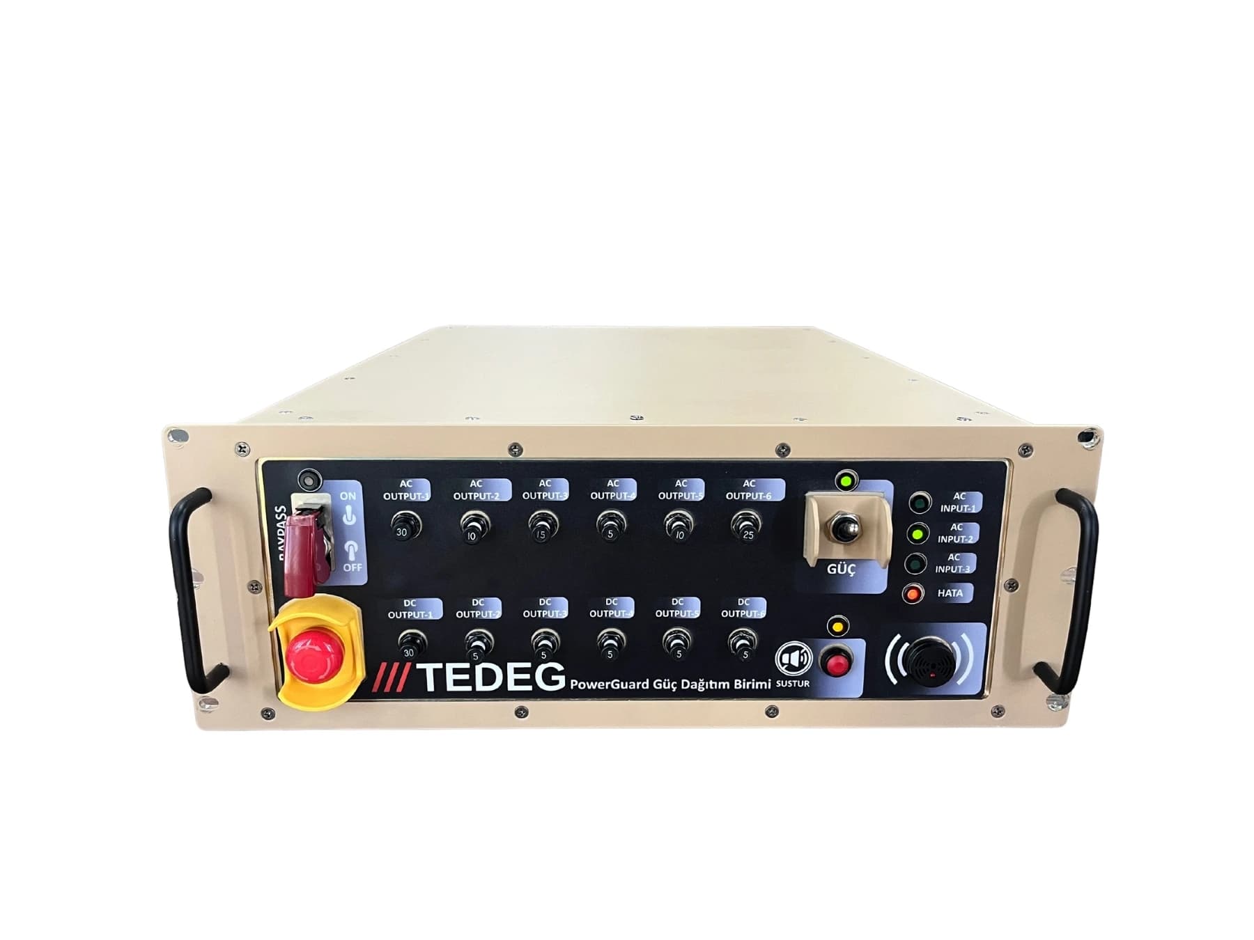
Land Platforms · 2024
Tactical Truck Power Architecture Modernisation
An ageing PDU that could no longer keep pace with growing mission loads was replaced by a remotely monitored power distribution architecture built on the PDU-RT5002 and designed to MIL-STD requirements.
Read case study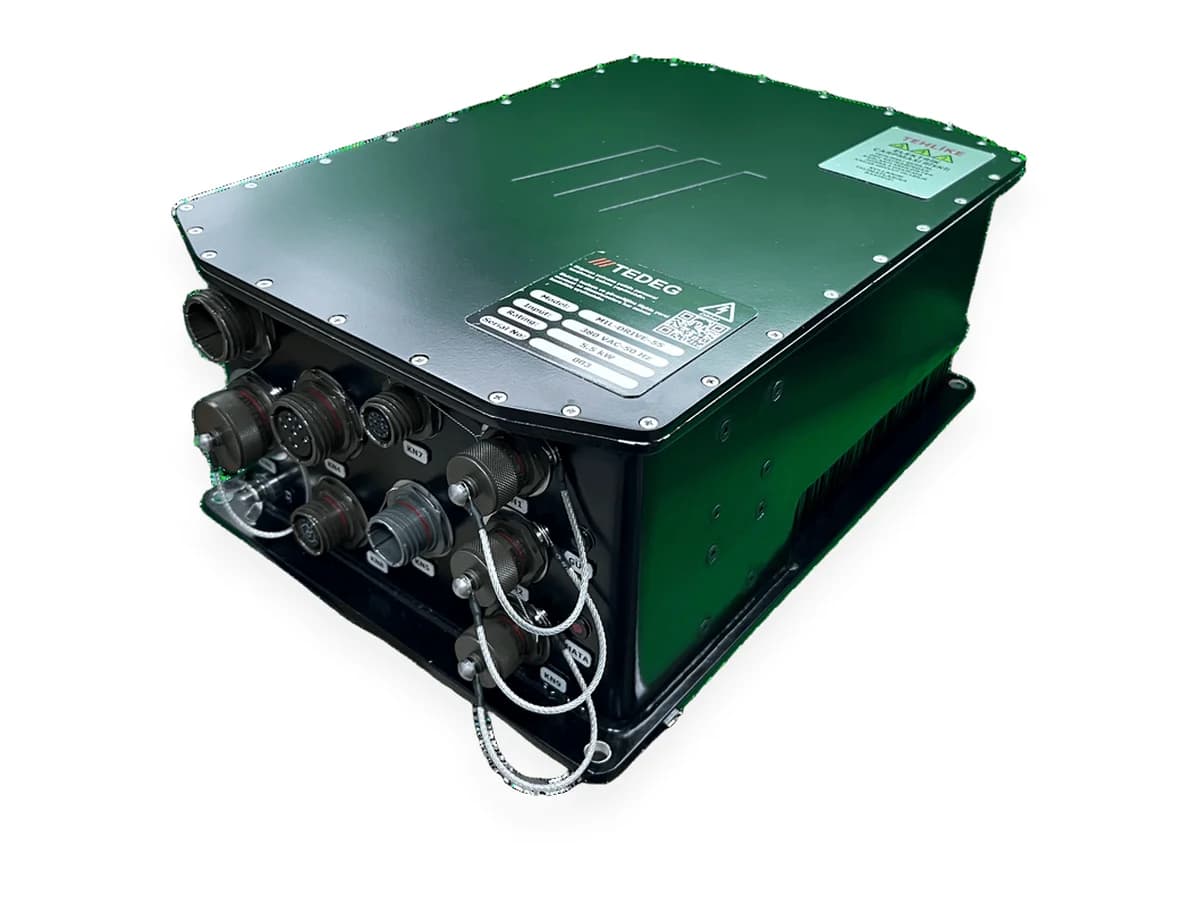
Air Defence · 2025
Mobile Air Defence Platform — Pedestal Motor Control & Radar Frequency Feed
A motor drive and a frequency converter sourced from separate foreign suppliers were replaced by a matched TEDEG pair, designed together so that neither interferes with the other.
Read case study