
Mil-Drive MCU-400 Military Motor Control Unit — Motor Drive, Power Distribution and Control in One Enclosure
Model
Mil-Drive MCU-400
Part number (P/N)
TDG-042-A0000
Input
3-phase 400 VAC + N + PE, 50–60 Hz, 10 A rms
Output
3-phase induction motor; FOC vector control; 0–50.0 Hz, ±1500 rpm
Output current
10 A rms continuous (≈ 6.9 kVA); induction motors up to 4 kW (400 V, 4-pole)
Speed feedback
Incremental encoder input (1024 PPR), closed-loop speed control
Ramps
Acceleration / deceleration 1.0–30.0 s, adjustable
Communication
RS-485 (4-wire, 115200 bps) · Ethernet 10/100 TCP/IP · embedded web interface
Connectors
7 × MIL-DTL-38999 Series III; M6 ground stud
Ingress protection
IP67
Company:ITAR-FreeNCAGE: TM885
Overview
Product and Purpose
Mil-Drive MCU-400 is a military motor control unit that powers, protects, drives and controls 3-phase 400 VAC induction motors from a single enclosure. It replaces an industrial variable frequency drive (VFD), a separate electrical panel, a PLC and the wiring between them with one outdoor-rated unit designed to MIL-STD-810H and MIL-STD-461F.
The unit combines a field-oriented control (FOC) vector drive, power distribution and protection, the mechanism's interlock and limit logic, a hand controller, RS-485 and an Ethernet web interface. It is designed and manufactured by TEDEG in Ankara; the photos show a pre-production unit.
Engineering Capability and Technology
The unit takes a 3-phase 400 VAC input and distributes power to the motor, heater and control circuits with overcurrent and short-circuit protection. Its integrated frequency drive runs the motor with FOC vector control in a closed loop with encoder feedback: 0–50.0 Hz output frequency, ±1500 rpm and 10 A rms continuous output current, which corresponds to induction motors up to 4 kW (400 V, 4-pole).
The mechanism's lock and limit switches connect directly to the unit. The control board monitors these inputs continuously and does not run the motor until all conditions for movement are met. The operator starts travel with a single touch; when the mechanism reaches its limit switch, the unit ramps the motor to a stop.
The unit is operated from the Mil-Drive HCU-400 military pendant control unit, the system control panel (RS-485) or the web interface over Ethernet, with command priority assigned automatically. All measurements, faults and settings are monitored and changed through the web interface; settings are stored in non-volatile memory.
Key specifications:
| Parameter | Value |
|---|---|
| Input | 3-phase 400 VAC + N + PE, 50–60 Hz, 10 A rms; input phase-loss detection, L1-L2 / L2-L3 / L3-L1 voltage monitoring |
| Motor output | 3-phase induction motor; FOC vector control; 0–50.0 Hz (0.1 Hz steps), ±1500 rpm; 10 A rms continuous (≈ 6.9 kVA); up to 4 kW (400 V, 4-pole) |
| Speed feedback | Incremental encoder input (1024 PPR), closed-loop speed control |
| Ramps | Acceleration and deceleration 1.0–30.0 s, adjustable |
| Braking | Regenerative dynamic braking (brake resistor channel); motor brake output |
| Control supply | Internal AC/DC converter, 28 VDC control circuits |
| Communication | RS-485 (4-wire, full duplex, 115200 bps) · Ethernet 10/100 TCP/IP · embedded web interface |
| Ingress protection | IP67 |
| Cooling | Natural convection (fanless); forced-air cooling optional |
| Dimensions | 350 × 245 × 146 mm (excluding connectors); mounting: 4 holes in the base flange, 330 × 225 mm pitch |
| Weight | 9.25 kg |
| Enclosure and paint | Aluminium and stainless steel; MIL-DTL-64159 compatible military paint: Green 383 (FED-STD-595B 34094) standard, Tan 686A (33446) and Earth Yellow (33245) optional |
One Box Instead of Drive + Panel
| Industrial drive + separate panel | Mil-Drive MCU-400 | |
|---|---|---|
| Parts | Drive, panel, PLC, wiring | One unit |
| Environment | Indoor, industrial | Designed to MIL-STD-810H, outdoor |
| EMC | Extra filters and work | Designed to MIL-STD-461F |
| Interlock logic | Written separately in a PLC | Built into the control board |
| Monitoring | Separate HMI/SCADA | Embedded web interface |
Connectors (MIL-DTL-38999)
| Connector | Type | Function | Voltage / current |
|---|---|---|---|
| KN1 | MIL-DTL-38999 Series III, 24WE06SN | Motor and heater power output | 400 VAC, 10 A rms |
| KN2 | MIL-DTL-38999 Series III, 24WE06PN | Power input (3-phase + N + PE) | 400 VAC, 10 A rms |
| KN3 | MIL-DTL-38999 Series III, 24WC35SN | Interlock and limit inputs – group 1 | 28 VDC |
| KN4 | MIL-DTL-38999 Series III, 24WB35SN | Interlock and limit inputs – group 2 | 28 VDC |
| KN5 | MIL-DTL-38999 Series III, 24WB35SN | Hand controller | 28 VDC + RS-485 |
| KN6 | MIL-DTL-38999 Series III, 24WB35SN | Ethernet 10/100 | Signal |
| KN7 | MIL-DTL-38999 Series III, 24WA35SN | RS-485 serial communication | Signal |
| GND | M6 stainless stud | Chassis ground, < 5 mΩ | — |
Pin assignments and the communication protocol are given in the interface control document (ICD); the connector layout can be adapted to the installation.
Control and Protection
| Function | Description |
|---|---|
| Interlock chain | Travel does not start until lock, limit and leveling conditions are met |
| Single-touch travel | One press starts travel, which stops automatically at the limit switch; a second press or the emergency stop interrupts it |
| Command priority | Hand controller when on; otherwise system control panel (RS-485); otherwise web interface |
| Travel timeout | If the set maximum run time is exceeded, the motor stops and a fault is raised |
| Emergency stop | IP67 button on the unit, the hand controller or a command; motor output is cut instantly, control and communication stay on |
| Protection | Input phase loss; motor output phase loss and short circuit; DC bus < 500 V / > 800 V; motor overload (150 % immediate, above 100 % for 30 s); brake current > 10 A; motor > 160 °C, heatsink > 120 °C, internal > 90 °C |
| Cold environment | Two-stage heating switches on below +10 °C and +24 °C |
Environmental and EMC Design Basis
| Parameter | Value |
|---|---|
| Operating / storage temperature | −35 °C … +50 °C / −45 °C … +65 °C (designed to MIL-STD-810H) |
| Altitude | 3,200 m (MIL-STD-810H Method 500.6) |
| Humidity, salt fog, fungus | Designed to Methods 507.6, 509.7, 508.8 |
| Vibration / shock | Method 514.8 Category 4 / 15.2 g, 5 ms (Method 516.8) |
| Rain / sealing | IP67; sealed design to MIL-STD-810G rain (Method 506.5) |
| EMC | Designed to MIL-STD-461F: CE102, CS101, CS114, CS115, CS116, RE102, RS103 |
Environmental and EMC values are the design basis; electrical values are verified in the factory acceptance test.
Typical Application Scenarios
- Antenna and sensor masts / platforms: raise and lower drive with interlock and limit chain
- Platform leveling and lifting mechanisms
- Winch, hatch and ramp drives
- Shelter and vehicle-mounted systems: 3-phase motor loads, one outdoor enclosure
Configuration and Ordering Code
Motor rated current, frequency, ramps and direction are set in software; the number of interlock/limit inputs and the travel sequence are adapted to the mechanism. The Mil-Drive HCU-400 pendant control unit and its cable (5 m standard) can be added to the order.
Ordering code example: MCU-400-E-H-C05-0 — Ethernet/web (-E), HCU-400 hand controller included (-H), 5 m controller cable (-C05), military green paint (-0). Add -F for forced-air cooling; paint codes 0 = Green 383, 1 = Tan 686A, 2 = Earth Yellow.
The TEDEG Advantage
MCU-400 brings the drive, panel, PLC and wiring that are otherwise installed separately in the field into one sealed unit: installation, testing and maintenance run through one part, with one supplier responsible. For higher power and Safe Torque Off, the Mil-Drive-55 military induction motor drive belongs to the same family. All products are in the Frequency Converters, Motor Drives & Military UPS Systems category; use the quote form for a project-specific configuration.
Specifications
| Model | Mil-Drive MCU-400 |
| Part number (P/N) | TDG-042-A0000 |
| Input | 3-phase 400 VAC + N + PE, 50–60 Hz, 10 A rms |
| Output | 3-phase induction motor; FOC vector control; 0–50.0 Hz, ±1500 rpm |
| Output current | 10 A rms continuous (≈ 6.9 kVA); induction motors up to 4 kW (400 V, 4-pole) |
| Speed feedback | Incremental encoder input (1024 PPR), closed-loop speed control |
| Ramps | Acceleration / deceleration 1.0–30.0 s, adjustable |
| Communication | RS-485 (4-wire, 115200 bps) · Ethernet 10/100 TCP/IP · embedded web interface |
| Connectors | 7 × MIL-DTL-38999 Series III; M6 ground stud |
| Ingress protection | IP67 |
| Operating temperature | −35 °C … +50 °C |
| Cooling | Natural convection (fanless); forced-air cooling optional |
| Dimensions | 350 × 245 × 146 mm (excluding connectors) |
| Weight | 9.25 kg |
| Standards | Designed to MIL-STD-810H and MIL-STD-461F |
MIL-STD Compliance
MIL-STD-810H
EnvironmentalMIL-STD-461F
EMI/EMCSee Certifications & Quality for our test and validation approach, and our Test & Validation service for programme-specific testing.
Datasheet
Related Products
Frequency Converters, Motor Drives & Military UPS Systems
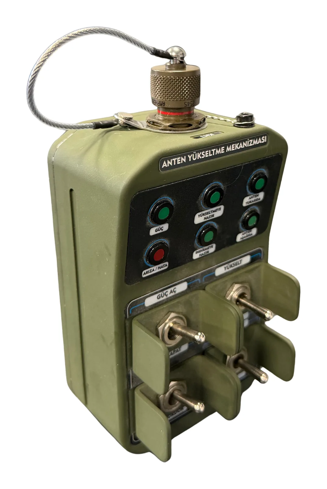
Mil-Drive HCU-400 Military Pendant Control Unit
Details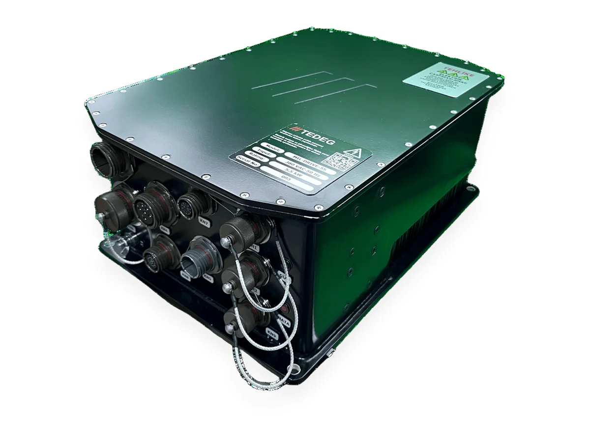
Frequency Converters, Motor Drives & Military UPS Systems
Mil-Drive-55 Military Induction Motor Drive — FOC Vector Drive
Details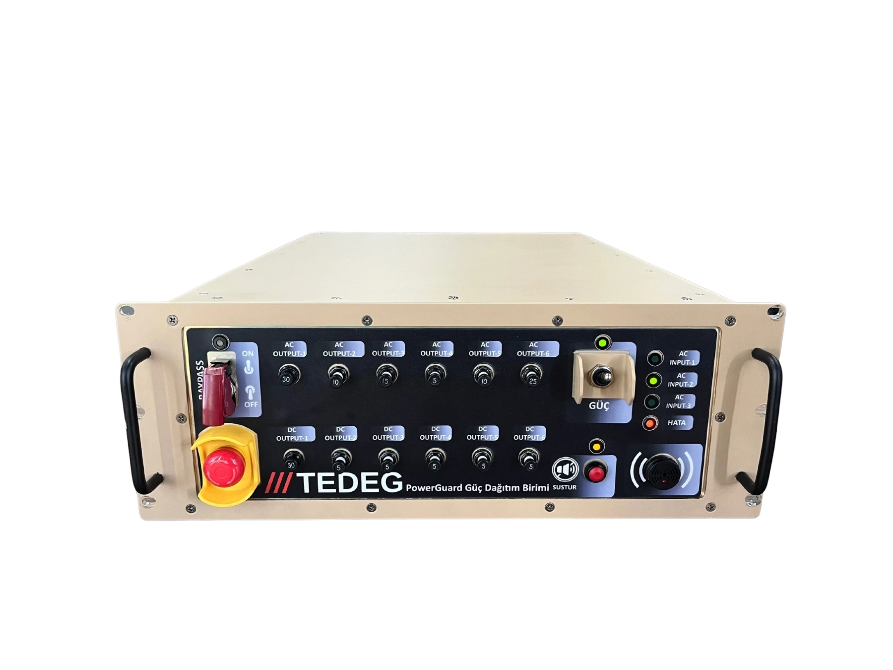
Power Distribution Units (PDU)
PDU-RT5002 Military Power Distribution Unit — Rack-Mount Rugged PDU
DetailsFull category: military frequency converters and 400 Hz power systems
Engineering Support
Our engineering services can adapt this product to your platform, integrate it or test it against your programme requirements.
Quality and Testing
FAQ
Which motors does it drive?+
3-phase 400 VAC induction motors: 10 A rms continuous output current, up to 4 kW on 400 V 4-pole motors. Speed is controlled in a closed loop with encoder (1024 PPR) feedback.
Does it replace an industrial drive and panel?+
Yes, that is its purpose: the drive, power distribution and protection, interlock and limit logic and monitoring in one IP67 unit. No separate PLC or HMI is needed.
Does the emergency stop cut communication?+
No. The emergency stop cuts the motor outputs instantly; the control board and communication stay on, and status messages keep coming.
What happens in the cold?+
Two-stage heating switches on below +10 °C and +24 °C. The operating temperature is −35 °C … +50 °C.
Can the software be adapted to my mechanism?+
Yes. The number of interlock/limit inputs, the travel sequence, motor rated current, frequency, ramps and direction are set in software for the mechanism.
Can the controller cable length be chosen?+
5 m is standard; other lengths on request. The cable can also be supplied separately under its own part number (TDG-042-02-xx).