
PowerGuard DC-PDCU-11 Military DC Power Distribution and Control Unit — 11-Channel Solid-State 28 VDC Rack PDU
Model
PowerGuard DC-PDCU-11
Part number (P/N)
TDG-049-A0000
Input
28 VDC nominal; MIL-STD-1275E referenced input protection
Outputs
11 × solid-state 28 VDC channels, 20 A per channel
Total output power
100 A total (2,800 W @ 28 VDC); software-adjustable current limit
Control
Embedded web interface · Ethernet TCP/IP · optional RCU-01 remote control unit
Sequencing
Power-up / power-down delay per channel, 10 ms resolution
Ingress protection
IP54
Operating temperature
−32 °C … +50 °C
Weight
9 ± 2 kg
Company:ITAR-FreeNCAGE: TM885
Overview
Product and Purpose
The PowerGuard DC-PDCU-11 is a 19-inch 2U rack-mount military DC power distribution and control unit. It distributes, protects and remotely controls loads fed from a 28 VDC vehicle or platform bus through 11 independent solid-state channels, each rated 20 A. An embedded web interface and an Ethernet TCP/IP control protocol monitor and switch every channel.
Sequenced power-up and power-down, adjustable alarm thresholds, a guarded emergency stop and a bypass mode give controlled power management in ships and surface platforms, shelters and 28 VDC military system cabinets. The unit is designed and manufactured by TEDEG in Ankara; the photos show a pre-production unit.
Engineering Capability
Every channel is solid-state switched: with no mechanical contactors or relays there is no contact wear, switching is silent, and current, voltage and temperature are measured continuously on each channel. Each channel has electronic over-current and short-circuit protection, and the voltage drop per channel is 0.5 V maximum.
Channels are switched from the front-panel buttons, from the embedded web interface, by the integrated system over the Ethernet TCP/IP control protocol, or from the optional PowerGuard RCU-01 remote control unit. A programmable power-up and power-down delay for each channel, with 10 ms resolution, energises the loads in sequence and prevents inrush peaks and bus collapse.
Technical specifications:
| Feature | Value |
|---|---|
| Input | 28 VDC nominal; MIL-STD-1275E referenced protection (reverse polarity, over-voltage, spikes, surges) |
| Input connectors | Single-pole high-current panel connectors, red (+) and black (−) |
| Outputs | 11 × solid-state controlled 28 VDC channels on 4 circular military connectors; 20 A per channel |
| Total output | 100 A total (2,800 W @ 28 VDC); total current limit adjustable in software |
| Protection per channel | Electronic over-current and short-circuit protection |
| Voltage drop per channel | 0.5 V maximum |
| Sequencing | Power-up and power-down delay per channel, 10 ms resolution; all ON / all OFF |
| Communication | Ethernet 10/100 (sealed RJ45): web interface and TCP/IP control protocol |
| Remote control | PowerGuard RCU-01 on a dedicated connector (supply + RS-485) |
| Own consumption | 50 W maximum with all channels on |
| Factory acceptance test | Total load of 50 A on 5 outputs for 5 minutes continuously |
| Dimensions | 19-inch rack, 2U (482.6 × 88.1 mm); depth 500 mm, including rack ears and front handles |
| Weight | 9 ± 2 kg |
| Ingress protection | IP54 |
| Paint | RAL 7038 polyurethane |
| Grounding | M5 ground stud; bonding resistance < 5 mΩ |
Front Panel
| No | Element | Function |
|---|---|---|
| 1 | Input fuse cover | Front access to the input fuse (80 A) |
| 2 | Emergency stop button | Mushroom button with yellow guard; cuts all outputs immediately |
| 3 | BYPASS switch | In the ON position outputs are not interrupted on an alarm; BYPASS LED lit |
| 4 | Channel buttons (11) | Channel ON / OFF; built-in LED shows the channel state; legends printed to the configuration |
| 5 | ALL ON / ALL OFF | Switches all channels on / off in the programmed sequence |
| 6 | SILENCE / BLANKING | Silences the audible alarm; held for 3 s, blanks the panel illumination |
| 7 | REMOTE | LOCAL / REMOTE selection; in REMOTE mode control is from the web interface, TCP/IP and the remote control unit |
| 8 | Audible alarm (buzzer) | Audible warning on alarm and emergency stop |
| 9 | ENERGY switch and power LED | Main power switch (ON / OFF); the green LED shows the unit is energised |
| 10 | Status LEDs | POWER, FAULT, BLANKING, COMM, BYPASS |
| 11 | Handles and rack ears | 19-inch rack mounting and handling |
Rear Panel and Connectors
| Connector | Type | Function |
|---|---|---|
| INPUT 1 / INPUT 2 | Single-pole high-current panel connectors, red / black | Main DC input (+ / −) |
| J1–J3 | Circular military connectors | Output channel groups 1–3 |
| J4 | Circular military connector, 4 contacts | High-current channel (two pin pairs in parallel) |
| J5 | Circular military connector | Remote control unit (RCU) link: supply + RS-485 |
| J6 | Sealed RJ45 | Ethernet 10/100: web interface and TCP/IP control protocol |
| GND | M5 grounding stud | Chassis ground; bonding resistance < 5 mΩ |
Connector types, pin assignments and the channel-to-connector mapping are given in the interface control document (ICD) and can be adapted to the customer's installation standard. Mating plugs are specified in the quotation.
Web Interface and System Integration
The control page shows the DC bus voltage, total current, number of channels on, device temperature, operating time and device status, with a channel table of channel temperature, input and output voltage and current. Each channel can be switched ON, OFF, reset or switched off with a delay, and all channels can be switched together.
The settings page is password-protected and holds the alarm thresholds, the power-up and power-down delays for each channel and the total current limit. All measurements and commands are also available for read and write access over the Ethernet TCP/IP control protocol; the interface document is supplied on request.
Alarms and Safety Functions
Alarm thresholds are adjustable in software. On an alarm the outputs are cut; in bypass mode they are not interrupted.
| Alarm | Default threshold | Return to normal |
|---|---|---|
| Bus voltage high | > 30 V | < 29 V |
| Bus voltage low | < 20 V | > 21 V |
| Internal temperature high | > 53 °C | < 50 °C |
| Internal temperature low | < 0 °C | > 4 °C |
| Communication loss | Approx. 10 s | When the link is restored |
| Emergency stop | Immediate, all outputs cut | Release the button and restart |
Environmental and EMC Design Basis
| Parameter | Value |
|---|---|
| Operating temperature | −32 °C … +50 °C |
| Storage temperature | −40 °C … +60 °C |
| Altitude | 0 – 3,000 m |
| High and low temperature | Designed to MIL-STD-810H Method 501.7 and 502.7 |
| Humidity | Designed to MIL-STD-810H Method 507.6, 95 % RH (non-condensing) |
| Salt fog | Designed to MIL-STD-810H Method 509.7 |
| Vibration | Designed to MIL-STD-167-1A (shipboard) |
| Shock | Designed to MIL-STD-810F Method 516.5 Procedure I |
| EMC | Designed to MIL-STD-461E surface-ship requirements: CE101, CE102, CS101, CS106, CS114, CS116, RE101, RE102, RS101, RS103 |
| Input power quality | MIL-STD-1275E referenced input protection |
Environmental and EMC values are the design basis; tests with an accredited laboratory (ISO/IEC 17025) report will be stated separately. Electrical values are verified in the factory acceptance test.
Typical Applications
- Ships and surface platforms: distribution and control of 28 VDC mission loads from one rack unit, with remote ON/OFF and emergency stop at the operator console
- 28 VDC military system cabinets: protected, individually switchable channels with sequenced power-up for loads with high inrush current
- Shelters and command systems: monitoring and control of every channel from the integrated system over Ethernet TCP/IP
Configuration Options and Ordering Code
| Option | Description |
|---|---|
| Number and rating of channels | 11 × 20 A standard; channel count and current rating can be adapted to project requirements |
| Input | Number of inputs and connector type to project requirements |
| Communication | Ethernet TCP/IP standard; additional interfaces on request |
| Remote control | PowerGuard RCU-01 and interconnection cable (length options) |
| Mounting | 19-inch rack standard; other mounting arrangements on request |
Ordering code: DC-PDCU-11-E-R: DC power distribution and control unit, 11 output channels, Ethernet TCP/IP (E), with the RCU-01 remote control unit (R); the cable length is specified separately.
The TEDEG Advantage
The DC-PDCU-11 combines distribution, protection, monitoring and remote control in a single 2U unit, so no separate relay panel, contactor box or monitoring module is needed in the cabinet. Channel count, current rating, input arrangement, connectors and communication interfaces can be adapted to the project, and 2D and 3D (STEP) drawings and an MTBF / MTTR analysis (MIL-HDBK-472) are available on request.
For distribution from several DC sources on a vehicle, see the military vehicle DC power distribution unit (TDG-EDP-D0X); for 220 VAC multi-source rack distribution, see the PDU-RT5002 military power distribution unit. The full range is in Power Distribution Units (PDU).
Specifications
| Model | PowerGuard DC-PDCU-11 |
| Part number (P/N) | TDG-049-A0000 |
| Input | 28 VDC nominal; MIL-STD-1275E referenced input protection |
| Outputs | 11 × solid-state 28 VDC channels, 20 A per channel |
| Total output power | 100 A total (2,800 W @ 28 VDC); software-adjustable current limit |
| Control | Embedded web interface · Ethernet TCP/IP · optional RCU-01 remote control unit |
| Sequencing | Power-up / power-down delay per channel, 10 ms resolution |
| Ingress protection | IP54 |
| Operating temperature | −32 °C … +50 °C |
| Weight | 9 ± 2 kg |
| Dimensions | 19-inch rack, 2U (482.6 × 88.1 mm); depth 500 mm |
| Standards | Designed to MIL-STD-810H · 461E · 167-1A |
MIL-STD Compliance
MIL-STD-1275E
28 VDC Vehicle Electrical SystemsMIL-STD-810H
EnvironmentalMIL-STD-810F
EnvironmentalMIL-STD-461E
EMI/EMCSee Certifications & Quality for our test and validation approach, and our Test & Validation service for programme-specific testing.
Datasheet
Related Products
Power Distribution Units (PDU)
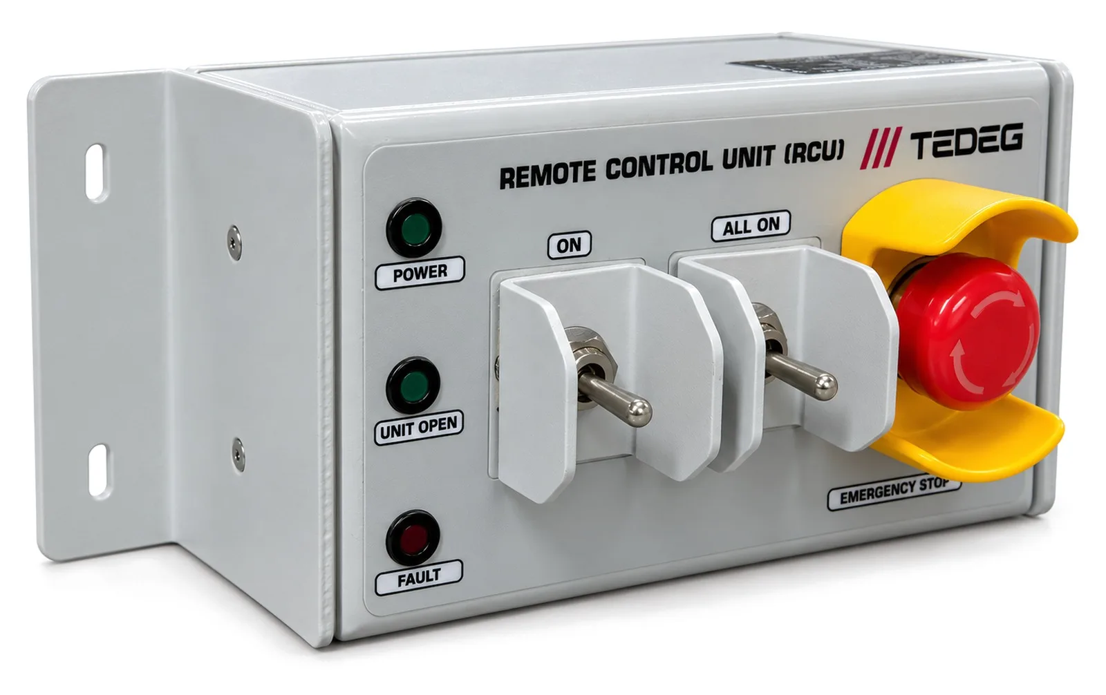
PowerGuard RCU-01 Remote Control Unit for Military PDUs
Details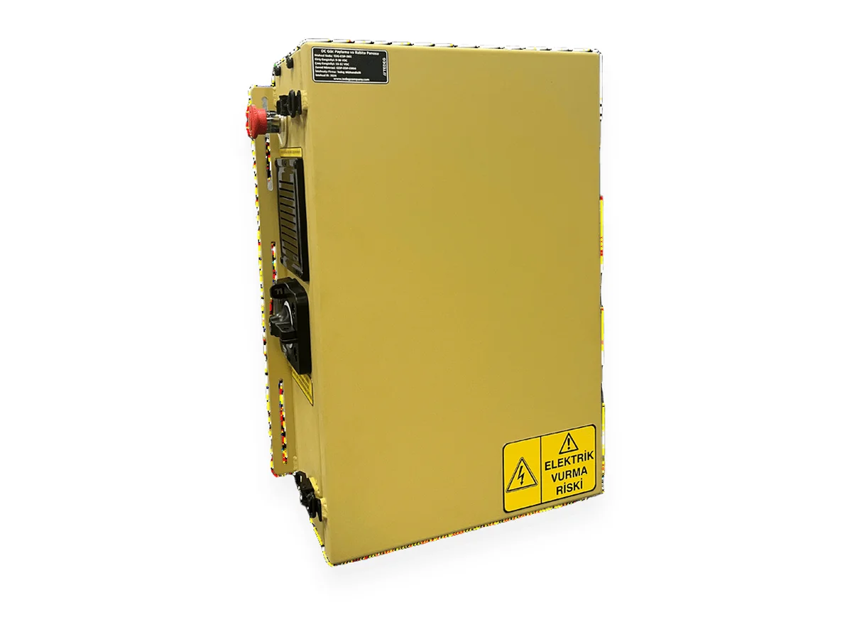
Power Distribution Units (PDU)
Military Vehicle DC Power Distribution Unit (28 VDC Vehicle PDU)
Details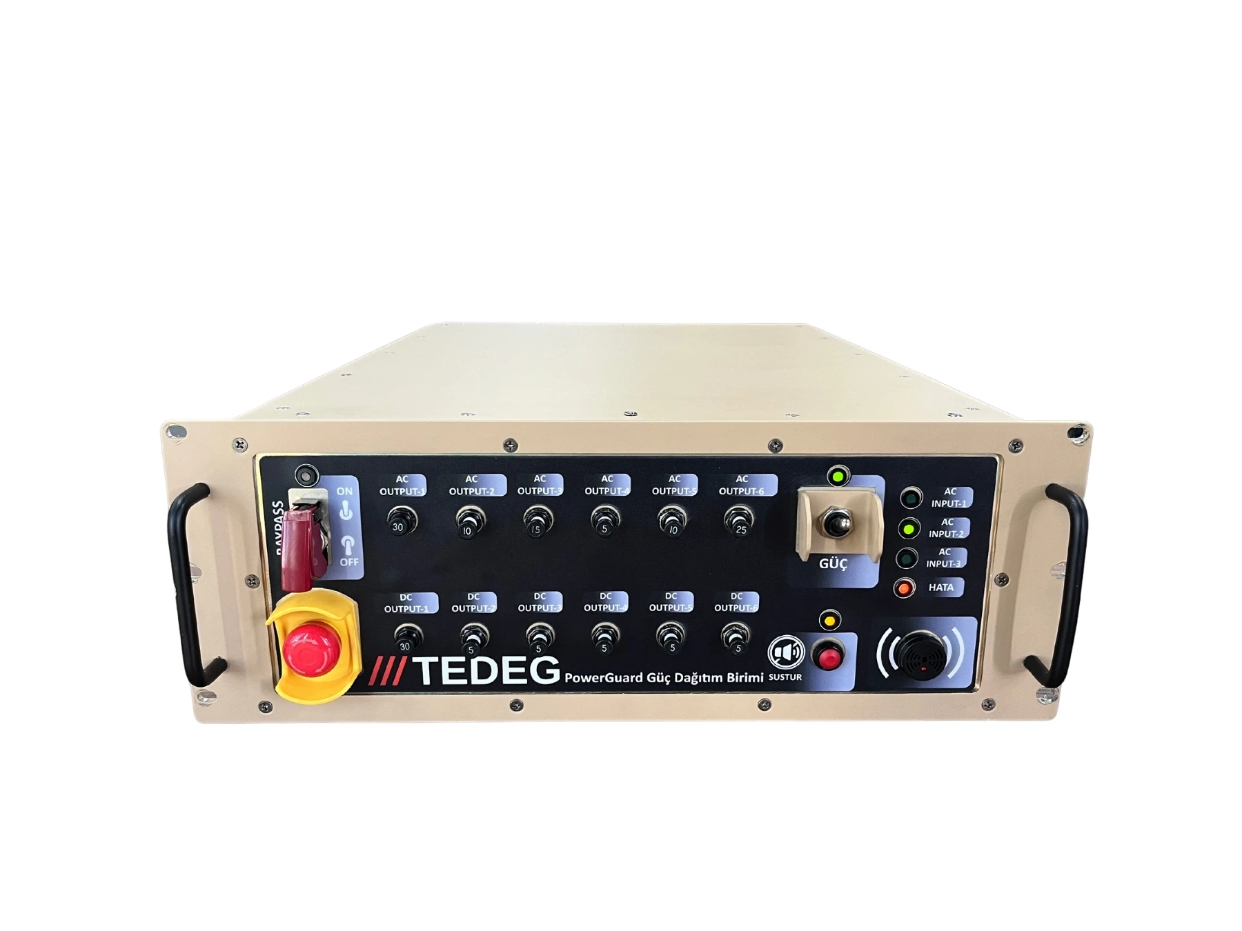
Power Distribution Units (PDU)
PDU-RT5002 Military Power Distribution Unit — Rack-Mount Rugged PDU
DetailsFull category: military power distribution units
Engineering Support
Our engineering services can adapt this product to your platform, integrate it or test it against your programme requirements.
Quality and Testing
FAQ
How many channels are there and how are they protected?+
There are 11 solid-state controlled 28 VDC output channels, rated 20 A per channel and 100 A in total (2,800 W at 28 VDC). Each channel has electronic over-current and short-circuit protection, and the voltage drop per channel is 0.5 V maximum. The total current limit is set in software.
From where are the channels controlled?+
From the front-panel buttons, the embedded web interface, the integrated system over the Ethernet TCP/IP control protocol, or the optional PowerGuard RCU-01 remote control unit. The LOCAL / REMOTE button selects whether the web interface, TCP/IP and RCU commands are active.
How does sequenced power-up work?+
A power-up and power-down delay with 10 ms resolution is programmed for each channel. On ALL ON / ALL OFF or the main power command, the channels come on and go off in that sequence, which prevents inrush peaks and bus collapse.
What happens on an alarm?+
Outputs are cut on bus-voltage, internal-temperature and communication-loss alarms; the thresholds are set in software. In bypass mode the outputs are not interrupted. The emergency stop cuts all outputs immediately.
Which standards is it designed to?+
Input protection is MIL-STD-1275E referenced, and the unit is designed to MIL-STD-810H (Methods 501.7, 502.7, 507.6, 509.7), MIL-STD-810F Method 516.5, MIL-STD-167-1A and the MIL-STD-461E surface-ship requirements. Tests with an accredited laboratory report are stated separately.
Can the configuration be adapted to my project?+
Yes. The channel count and current rating, the number of inputs and the connector type, additional communication interfaces and the mounting arrangement can be adapted to project requirements. Send your requirements through the quote form.