
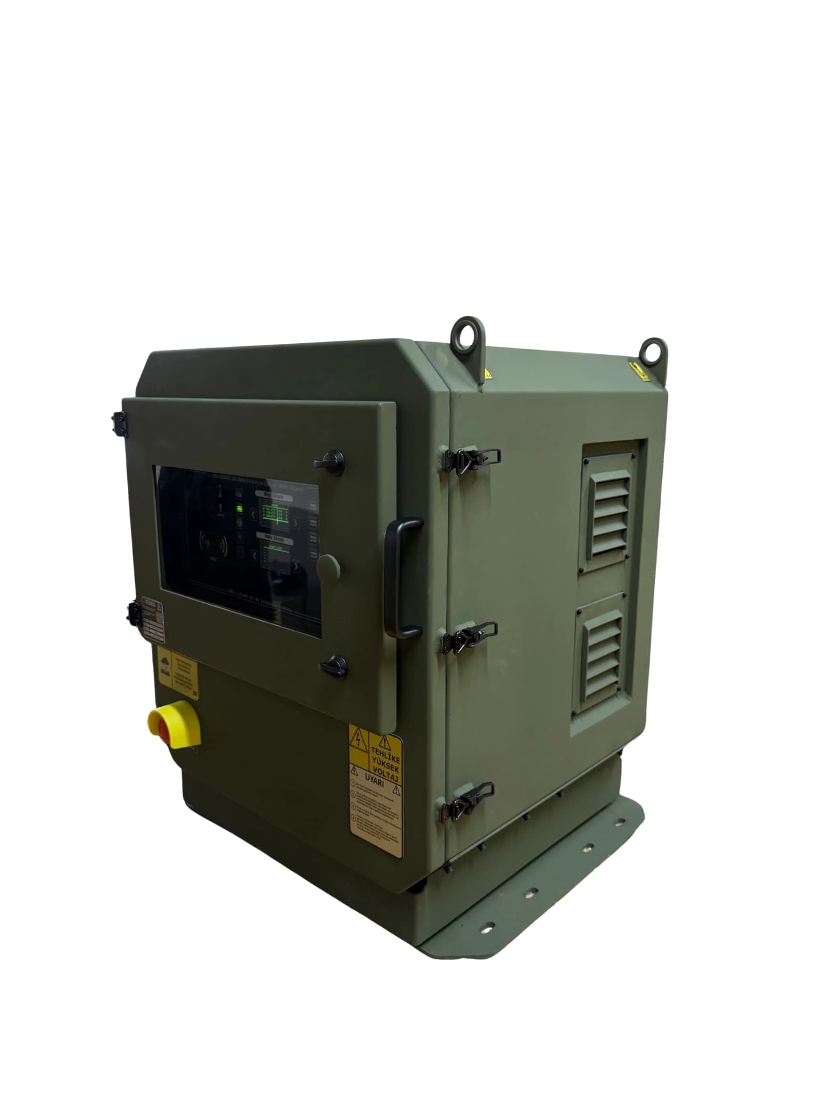
The Role of AC-AC Conversion in Modern Military Systems
Modern military platforms host dozens of electronic subsystems running at different voltage and frequency levels. A mobile command centre is fed with 400 VAC three-phase power from a generator, while inside it radios, mission computers, navigation systems and sensitive medical equipment need 115 VAC. The same applies on naval platforms: a conversion layer is needed between the ship's auxiliary network and 115 VAC communications and radar equipment.
The military AC-AC inverter is the conversion link in this chain: it turns AC power at one voltage and frequency level into a stable, isolated AC output that withstands electromagnetic interference at another level. A civilian AC-AC converter may do the job in industrial applications, but military field conditions (vibration, EMI, environmental stress, ground loops) demand much more.
400 V and 400 Hz Are Not the Same Thing
The two terms most often confused in military power conversion are 400 V and 400 Hz. The "400/115 VAC" in this guide describes a voltage conversion: a 115 VAC three-phase output is derived from a 400 VAC three-phase network. 400 Hz, on the other hand, is a frequency, and many military systems require a 115 VAC 400 Hz supply.
Why is 400 Hz used?
- Smaller, lighter magnetics: The core cross-section and number of turns a transformer needs for a given voltage are inversely proportional to frequency. Moving from 50 Hz to 400 Hz makes transformers and inductors markedly smaller. In return, core losses rise, so thinner laminations or special core materials are needed.
- Compact, high-speed motors: Synchronous speed is proportional to frequency (n = 120·f / p). A two-pole motor turns at 3,000 rpm on 50 Hz and 24,000 rpm on 400 Hz. The same power comes from a much smaller frame, raising power density.
- Easier filtering: The ripple on DC rectified from 400 Hz is at a much higher frequency. Filter capacitors and chokes in the power supplies of radar and weapon systems become smaller.
- Synchro and resolver reference: The angle-measuring elements in fire-control and navigation systems have traditionally run on a 400 Hz reference.
400 Hz has a cost too: line reactance rises with frequency, so voltage drop grows on long cable runs. That is why 400 Hz power is usually generated close to the load — in a ship's compartment, inside a vehicle or in a field shelter.
Typical 400 Hz users: radar, fire-control and weapon systems on ships; mobile radar and sensor systems; weapon turrets and stabilisation drives; mission electronics on some military land vehicles; test and calibration rigs for military equipment.
The TEDEG family when 400 Hz is needed
- PowerGuard 115/200 VAC 400 Hz Static Frequency Converter — variable 115–220 VAC, 60–400 Hz output from a 3-phase 360–440 VAC input; 115 VAC 400 Hz in star or delta connection
- PowerGuard Outdoor 60/400 Hz Frequency Converter — 12 kVA for outdoor use, 7 isolated outputs (5 × 60 Hz + 2 × 400 Hz)
- AC-AC Frequency Converter Transformer System — a 12 kVA system combining transformer, frequency converter and distribution in one cabinet; 2 × 400 Hz and 5 × 60 Hz outputs
- PowerGuard TPS-115 — 3-phase 115 VAC 400 Hz (600 VA) and 3 × isolated 28 VDC (600 W total) from a 230 VAC supply
For more on dual-frequency mobile systems, see our Mobile Military Frequency Converter Guide. How a static frequency converter turns 50 Hz into 400 Hz is explained in What Is a Static Frequency Converter?. To choose the right 400 Hz source for land, naval and radar systems, see 115 VAC 400 Hz Power Supply Selection.
AC-AC Conversion Topologies
Military AC-AC conversion uses three fundamental topologies:
1. Passive Transformer (Oldest Topology)
- Operation: Magnetic conversion only — primary winding 400 V, secondary 115 V
- Advantage: Simple structure, low cost, no moving parts, long life
- Disadvantage: Cannot convert frequency (50 Hz in, 50 Hz out), grid disturbances reach the load, high weight
- Use: Fixed installations that only need voltage conversion
2. Rotary Frequency Converter (Motor-Generator)
- Operation: Input motor → mechanical shaft → output generator
- Advantage: Full galvanic isolation, inherent harmonic filtering, frequency conversion possible
- Disadvantage: Moving parts, noise, periodic maintenance, very high weight
- Use: Fixed installations and older shipboard power systems — heavy and maintenance-intensive for mobile platforms
3. Static Inverter (Modern Mil-Spec)
- Operation: AC ⇒ DC (rectifier) ⇒ DC link ⇒ AC (IGBT PWM inverter) ⇒ isolation transformer
- Advantage: High efficiency, no moving parts, lighter, wide input-range tolerance, output isolated from grid disturbances
- Disadvantage: Complex electronics, higher development cost
- Use: The standard choice for modern mil-spec mobile platforms
Galvanic Isolation — Why It Is Non-Negotiable
Galvanic isolation means there is no direct electrical contact between input and output. The output transformer forms a magnetic link between the primary and secondary windings; energy is transferred only through the magnetic field, with no galvanic bond between conductors.
Practical Benefits
1. Ground-Loop Immunity
When several electronic systems inside a military vehicle are bonded to the same chassis ground, ground-loop currents arise. These currents:
- Cause interference (RFI) in radio and communications systems
- Corrupt sensitive sensor measurements
- Can cause false triggering in the mission computer
A galvanically isolated inverter lets the loads on the output side operate on their own separate ground plane, so ground-loop currents do not reach them.
2. Protection Against Voltage Surges
In the field, lightning-induced surges and switching transients on the network can cause high-voltage spikes on the input side. Galvanic isolation largely limits these spikes from passing to the output and protects critical electronics on the load side.
3. Personnel Safety
When working on the output side, the operator is isolated from the 400 V input hazard. This is an important safety advantage during field maintenance and intervention.
4. Compatibility with Shipboard Networks
Shipboard electrical networks are often operated ungrounded (isolated). A converter that galvanically separates the load side from the network limits the extent to which an earth fault in one item of equipment affects the whole network, and allows a separate earthing arrangement on the load side.
In the TEDEG PowerGuard 400/115 VAC AC-AC Military Inverter, galvanic isolation is provided by the output transformer.
Multiple Isolated Outputs — Controlled Load Distribution from One Unit
A single output is no longer what users expect from a modern military AC-AC inverter. A mobile command container carries several types of load:
- Radio / communications — needs sensitive, EMI-clean power
- Sensors and measurement — need low-noise, stable power
- Control computers — need high overload tolerance
- Lighting and heating — simple, robust loads
Connecting all of these to the same output causes operational problems: a fault in one load affects the others, and noise from one device disrupts communications.
What a multiple isolated output architecture provides:
- Outputs electrically separated from each other
- A fault on one output does not affect the other load groups
- Each output can be switched independently from the operator panel or remotely
- Real-time monitoring per output
The TEDEG PowerGuard 400/115 offers 4 isolated outputs: 3.6 + 2.4 + 2 + 2 kVA = 10 kVA in total. This allocation can be modularly redistributed to suit project requirements. Over Ethernet, each of the 4 outputs can be switched on and off independently, and real-time voltage and current values can be monitored.
Three-Layer Protection Architecture
Mil-spec inverters do not rely on a single protection layer. Three layers work together:
1. Hardware Layer
- Circuit breakers, fuses, surge suppression components
- Physical intervention against overcurrent, overvoltage and short circuit
- Thermal safety switches
2. Software Layer
- Microprocessor-based continuous monitoring
- Real-time voltage, current and frequency measurement
- Algorithmic overload detection
- Automatic output on/off logic and alarm thresholds
3. Mechanical Layer
- Cabinet design that damps vibration
- Cable management that prevents short circuits
- Airflow for thermal protection
- Sealing against dust and moisture
When these three layers work together, a fault in one layer is caught by the others. The PowerGuard 400/115 likewise has a three-layer protection architecture made up of hardware, software and mechanical layers.
Built-In Test (BIT) — Automatic Health Check
A modern military system must be able to check its own health before it is put into service. Built-In Test (BIT) is the combination of hardware and software that makes this possible. In the industry, BIT is usually treated in three stages:
- Power-On BIT: Automatic checks at switch-on
- Periodic BIT: Checks at set intervals during operation
- Initiated BIT: A comprehensive test started manually by the operator, for example before maintenance
In the PowerGuard 400/115, BIT performs an automatic health check before operation. Results are shown on a dual OLED display with separate info and fault screens, and the BIT result can also be viewed remotely over Ethernet. Maintenance staff can therefore assess the system's condition without connecting test equipment.
Typical Platform Applications
PowerGuard 400/115 class military AC-AC inverters serve the following platforms:
- Mobile command-and-control vehicles — 115 VAC equipment supply inside the field C2 container
- Naval platforms — frigates, patrol boats, naval radar stations
- Forward operating bases — tactical trucks, field communications vehicles
- Mobile radar and communications vehicles — isolated power for sensitive electronics
- Field hospital containers — supply for critical medical equipment
- Telecom shelters and relay stations — 115 V equipment supply from a 400 V network
- Test and calibration laboratories — precise 400 V → 115 V conversion
- Field IT and data centre containers — 115 V critical IT supply from a 400 V source
The TEDEG PowerGuard 400/115 Advantage
The TEDEG PowerGuard 400/115 VAC AC-AC Military Inverter offers the following combination in a single package:
- 3-phase 400 VAC, 50/60 Hz input → 3-phase 115 VAC, 50 Hz output
- 10 kVA total capacity across 4 independent isolated outputs (3.6 + 2.4 + 2 + 2 kVA)
- Galvanic isolation via the output transformer
- ≥ 85% efficiency
- Overload capability: 125% (5 min) · 200% (5 s) · 250% (1 s)
- Three-layer protection (hardware + software + mechanical)
- Ethernet remote monitoring and control — HTTP web interface, SNMP v2c/v3 and Modbus TCP via the KN6 port
- Dual OLED display (Info + Fault) and BIT
- MIL-DTL-38999 and MIL-DTL-5015 military connectors
- MIL-STD-1399B · MIL-STD-810G · MIL-STD-461G compliance standards
- −30 °C to +50 °C operating temperature, 160 ± 5 kg weight
On request, 440 VAC input or 60 Hz output variants can be offered through engineering customisation. If frequency conversion is also required, see the 400 Hz solutions listed above and the Frequency Converters, Motor Drives & Military UPS Systems category.
Corporate assurance: TEDEG Defence is an approved supplier of ASELSAN, Roketsan and the Turkish Ministry of National Defence (MSB), with NATO supplier registration under NCAGE: TM885.
Total Cost of Ownership (TCO)
The purchase price of a military AC-AC inverter is only part of its life-cycle cost. The other items are:
- Installation — the integrator's engineering hours, cable harness fit
- Maintenance — periodic inspections, capacitor and seal checks
- Spare parts — power modules, control boards, fuses
- Training — for operators and maintenance personnel
Remote monitoring and BIT shorten fault-finding and so directly affect the maintenance item. Working with a domestic manufacturer also keeps the point of contact for technical support, documentation and spare parts within Türkiye.
Conclusion
Military AC-AC inverter systems are the critical power-conversion layer of mobile defence platforms and fixed military infrastructure. 400/115 VAC conversion, galvanic isolation, multiple isolated outputs, MIL-STD-1399B compliance, three-layer protection and Ethernet remote control are the main features to look for in a serious mil-spec AC-AC inverter. If the loads need 400 Hz, frequency conversion must be planned alongside voltage conversion.
The TEDEG PowerGuard 400/115 delivers these features in a single package. For datasheet and technical documentation requests, visit the PowerGuard 400/115 product page; for an engineering conversation with our team, use the contact page.