400 Hz Converter Sizing: What Does the kVA Rating Actually Tell You?
400 Hz converter sizing is the first calculation radar, missile-system and naval integrators should settle before requesting a quote. Load lists arrive in watts, converters are rated in kVA, and in between sit power factor, inrush, simultaneity, phase balance and environment. Skip one and you get either an oversized cabinet or a converter that trips on the first motor start.
Below, frequency converter kVA calculation is worked through from the load list. For the unit's internals see What Is a Static Frequency Converter?; for connection type and application see 115 VAC 400 Hz Power Supply Selection. Here the only question is: how many kVA?
kVA vs kW
A converter's inverter stage is designed for a given current at a given voltage, so the limit is apparent power (kVA), not real power (kW). Power factor links the two:
| Quantity | Formula | Note |
|---|---|---|
| Apparent power | S (kVA) = P (kW) / PF | What loads the converter |
| Three-phase, star | I = S / (3 × V line-to-neutral) | V = 115 V in a 115/200 VAC system |
| Three-phase, delta | I = S / (√3 × V line-to-line) | V = 115 V in a 115 VAC line-to-line system |
| Single-phase | I = S / V | Compared against that phase's own capacity |
The same kVA gives different line currents by connection: a 4 kVA three-phase load draws about 11.6 A per phase in star (115 V line-to-neutral) and about 20.1 A in delta (115 V line-to-line).
Power Factor: How Low-PF Loads Grow the Converter
A 0.3 power factor example
As power factor falls, kVA rises for the same kW. A 1.5 kW load needs about 1.9 kVA at a 0.8 power factor, but 5.0 kVA at 0.3. At 0.3, the converter sees roughly 3.3 times the kW figure. Capacitor-input electronics and lightly loaded motors belong here.
Capacitive loads and harmonic current
Direction matters too. Capacitive (leading) loads destabilise some inverters, so check the datasheet for load power factor range and capacitive load support. Rectifier loads draw non-sinusoidal current, raising RMS current and heating; converter THD is usually quoted on a linear load, so raise this at quotation stage for rectifier-heavy systems.
Inrush and Peak Current
Even with the continuous kVA right, short peaks stress the converter:
- Motor starting: fan, pump and drive motors typically draw several times their rated current while starting.
- Capacitor charging: input capacitors of electronic loads draw a brief high current at first energisation.
- Transformer magnetising inrush: load-side transformers can far exceed rated current in the first cycles (one 400 Hz cycle is 2.5 ms).
These peaks are checked against the converter's overload window. The PowerGuard Outdoor datasheet, for example, gives 125% → 5 min, 200% → 5 sec and 250% → 1 sec at 0.8 PF. Where a datasheet has no overload-duration table, ask for one in writing.
The cheapest fix is often sequencing: start the largest motor first and the electronics afterwards, so its peak does not stack on the other loads.
Simultaneity, Operating Modes and Phase Balance
Not every load always runs at full power simultaneously. List the operating modes (standby, mission, maintenance/test), total the kVA for each and size for the heaviest. On radar test benches all loads often run together, so the diversity factor is 1.
With single-phase 400 Hz loads on a three-phase output, the most loaded phase sets the limit. A 6 kVA output has about 2 kVA per phase; put two of three 1.5 kVA single-phase loads on one phase and it sees 3 kVA, overloaded although the total is only 4.5 kVA.
Environment: Temperature, Altitude and Cabling
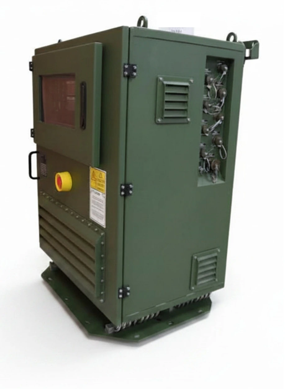
A converter's rating applies within its datasheet temperature and altitude limits. Shelter air can be hotter than outside; beyond the limits, ask for a derating curve. For comparison, PowerGuard Outdoor is specified for −32 to +55 °C and 3000 m, and the 400 Hz static frequency converter PowerGuard 115/200 VAC for −30 to +50 °C and 3000 m.
Cabling matters specifically at 400 Hz: reactance is proportional to frequency, so a cable has eight times the inductive reactance at 400 Hz that it has at 50 Hz. Long runs drop more voltage, so placing the converter near the load is part of sizing.
Worked Example: Radar Maintenance and Test Bench
These are generic figures to show the method, not project data. Three loads expect three-phase 115 VAC line-to-line (delta) 400 Hz and all run together during testing:
| Load | Power (kW) | Power factor | kVA | Starting |
|---|---|---|---|---|
| A — Transmitter and processor power supply | 2.1 | 0.70 | 3.0 | Brief capacitor charging |
| B — Cooling fan motor | 0.8 | 0.80 | 1.0 | 4.0 kVA for ≈1 s in this example |
| C — Display, control and reference electronics | 0.9 | 0.60 | 1.5 | — |
| Total | 3.8 | ≈0.69 | 5.5 |
- 1.Continuous load: 5.5 kVA. Line current at 115 V delta is about 27.6 A.
- 2.Growth margin: 25% in this example → about 6.9 kVA.
- 3.Peak check: if B starts while A and C are running, the brief total is 3.0 + 1.5 + 4.0 = 8.5 kVA. If B starts first, the peak stays at 4.0 kVA.
Mapping the result to products
- PowerGuard 115/200 VAC Static (8 kVA): 6.9 kVA with margin fits within 8 kVA, output set to delta 115 VAC 400 Hz. The 8.5 kVA peak exceeds the rating: start the fan first or confirm short-term overload capability with the manufacturer. The datasheet gives output power factor as min. 0.85 star and min. 0.80 delta; with the example at ≈0.69, how the rating applies is clarified at quotation stage. Time to steady state is 200 ms.
- PowerGuard Outdoor (12 kVA at 0.8 PF): 400 Hz loads go on two three-phase outputs of 4 kVA each (KN7, KN8). A and B together would fill one output at 4.0 kVA with no margin, so A takes one (3.0 kVA) and B and C the other (2.5 kVA). The overload figures are for the unit, so ask about per-output peak capability for B's start.
- AC-AC Frequency Converter Transformer System (12 kVA): for delta loads on a platform wanting CAN-Bus monitoring, the same split uses its two line-to-line (delta) 115 VAC 400 Hz outputs. The 12 kVA is shared across all seven outputs, so 60 Hz loads count too.
- PowerGuard TPS-115 (600 VA): too small here; load C alone exceeds 600 VA. It suits on-vehicle mission electronics needing a few hundred VA of 400 Hz plus 3 × isolated 28 VDC (600 W total).
For uninterrupted low power factor loads on the 60 Hz side, the military UPS system MIL-UPS-2K3 delivers 115 VAC 60 Hz pure sine, is rated 2.3 kVA, supports capacitive loads down to a 0.3 power factor, and gives 30 minutes of backup at a 2 kW load. A UPS does not produce 400 Hz; 400 Hz loads are fed by the converter.
What to Put in the Specification
For comparable quotes, the specification should state in numbers:
- kW, power factor (inductive/capacitive) and number of phases for each load
- Connection type: star (115 VAC line-to-neutral) or delta (115 VAC line-to-line)
- Operating modes and the simultaneous loads in each
- Largest inrush current, its duration and the start-up sequence
- Phase allocation of single-phase loads
- Temperature, altitude and cable length at the installation point
- Required growth margin and number of converter outputs
All options: military frequency converters.
400 Hz Frequency Converter Manufacturer in Turkey: TEDEG Defence
TEDEG Defence, based in Ankara, designs and manufactures 400 Hz frequency converters for land, naval and radar systems.
| Profile | Details |
|---|---|
| Company | TEDEG Defence Industry A.Ş. |
| Headquarters | Ankara |
| Founded | 2023 |
| Registrations and certificates | ISO 9001, EYDEP |
| Cluster memberships | OSSA, SAHA Istanbul |
The 400 Hz products in this article:
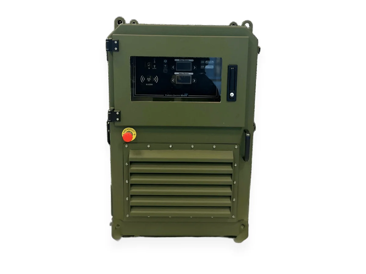
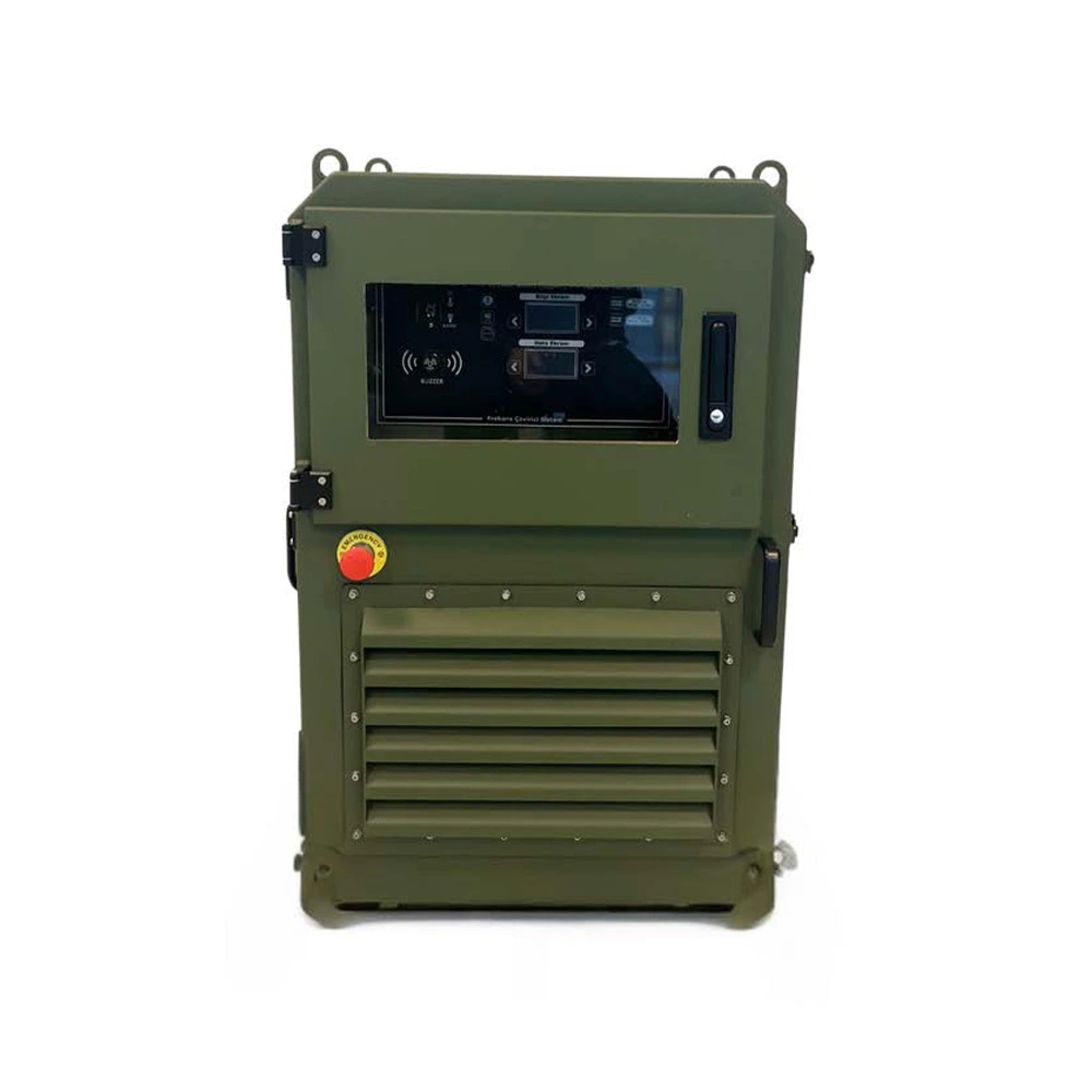
- PowerGuard 115/200 VAC 400 Hz Static: 8 kVA; variable 115–220 VAC, 60–400 Hz from a 3-phase 360–440 VAC input; star or delta 115 VAC 400 Hz.
- PowerGuard Outdoor: 12 kVA (0.8 PF), 2 × 4 kVA 400 Hz and 5 × 60 Hz isolated outputs.
- PowerGuard TPS-115: 3-phase 115 VAC 400 Hz 600 VA + 3 × isolated 28 VDC; −40 to +55 °C.
See Certifications & Quality and the product catalogue.
Frequently Asked Questions
How do you convert kW to kVA for a 400 Hz load?
kVA = kW / power factor. A load drawing 2.1 kW at a 0.70 power factor needs 3.0 kVA. If it is unknown, ask the load manufacturer.
How big a converter does a 0.3 power factor load need?
Apparent power is about 3.3 times the kW figure: a 1.5 kW load needs 5.0 kVA. Also confirm, from the datasheet or the manufacturer, that the converter is stable on capacitive loads and at what power factor its rating is defined.
How much margin should I leave for motor starting?
Compare the starting peak (kVA and duration) with the converter's overload window rather than using a fixed percentage. If it exceeds the window, try sequenced start-up, then a soft starter, then a larger converter.
How are single-phase 400 Hz loads spread on a three-phase converter?
Each phase carries about one third of the output capacity; spread loads by kVA so the most loaded phase stays within it.
Conclusion
400 Hz converter sizing comes down to four questions: what is the continuous kVA including power factor, how large and how long is the biggest peak, how are the loads spread over phases and outputs, and what environment will the unit work in? Written into the specification as numbers, they make quotes comparable.
Send your load list via the quotation form or contact our engineers; we will check the sizing with you.
Field example: for an application where low power factor loads were solved with a UPS and frequency converter together, see the missile and radar systems case study.