What Is a Multiple Smoke Grenade Launcher Configuration?
A multiple smoke grenade launcher is a vehicle screening system in which several launcher tubes are arranged at set angles and fired from one control unit. When smoke grenade launcher systems are specified, the real engineering decision is less "which product" than "which configuration": how many launchers, what coverage arc, where on the vehicle and in which firing groups?
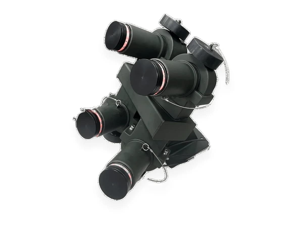
This article covers only those four decisions. Operating principle, calibre and munitions are in our 76 mm smoke grenade launcher systems guide. Worked values come from the datasheet of the TEDEG 76 mm Smoke Grenade Launcher System TDG-76-SGL, which is fitted with a minimum of 4 and a maximum of 16 launchers and configured to provide 90°, 120°, 180° or 360° smoke coverage.
The Four Decisions Behind Every Configuration
A smoke launcher configuration combines four variables, and none can be chosen in isolation:
- Coverage arc: the sector the screen has to close, set by the vehicle's role and the expected threat direction.
- Launcher count: how densely that sector is filled and how many salvos are available without reloading.
- Layout: turret or hull, and in which banks; set by platform geometry.
- Control and grouping: which launchers fire on which command; set by the crew's concept of use.
The order matters: arc first, then count, then layout, and grouping last.
Choosing the Coverage Arc: 90°, 120°, 180° or 360°
The TDG-76-SGL offers four coverage arcs, each with its own typical logic:
| Coverage arc | Typical use | Point to watch |
|---|---|---|
| 90° (one direction) | Small platforms expecting a threat from one side | Flanks and rear stay open |
| 120° (front and limited flanks) | Light reconnaissance vehicles | Withdrawal route must stay behind the screen |
| 180° (half perimeter) | Broad cover against a known threat direction | On a turret, the screen swings with the turret |
| 360° (full perimeter) | Fighting and command vehicles, built-up areas | Needs the most launchers and layout care |
The first question is what the vehicle will do after firing. A reconnaissance vehicle that withdraws may need only 120° to its front; a command vehicle that stays in place can be observed from any direction and needs the full perimeter. Naval platforms follow the same logic with port and starboard sectors.
Launcher Count: Deciding Between 4 and 16
Launcher count serves two needs: filling the chosen sector densely enough and, where required, holding tubes back for a second salvo. For a rough first estimate, divide the sector width by the number of launchers; the result is the angle between neighbouring launcher axes.
| Coverage arc | 4 launchers | 8 launchers | 12 launchers | 16 launchers |
|---|---|---|---|---|
| 90° | 22.5° | ≈ 11° | 7.5° | ≈ 5.6° |
| 120° | 30° | 15° | 10° | 7.5° |
| 180° | 45° | 22.5° | 15° | ≈ 11° |
| 360° | 90° | 45° | 30° | 22.5° |
This table is geometry, not a performance figure: whether a given spacing gives an unbroken screen depends on the munition's cloud width and throw distance. As the arc widens, launcher count must rise to keep the same density; in a narrow sector, a high count can instead reserve tubes for a second salvo.
Typically, heavy fighting vehicles carry 8–12 launchers, while lighter armoured personnel carriers and mine-resistant vehicles carry 4–8. The TDG-76-SGL takes 4 to 16; the same launcher and control architecture scales from a 4-launcher directional screen to full 360° coverage with 16 launchers.
Layout: Turret or Hull?
The same count and arc can be installed in two ways:
- Turret-mounted: the launchers turn with the turret and the screen is thrown where the weapon faces, so directional configurations (90°–180°) stay flexible with few launchers. In return, cabling passes through the turret's rotary joint, and roof space is shared with optics, antennas and the searchlight.
- Hull-mounted: the launchers are fixed relative to the vehicle's heading; the natural choice for turretless vehicles and full-perimeter configurations. Cabling is simpler, but screen direction depends on how the vehicle stands.
Points to check on the layout drawing:
- No hatch, periscope, antenna, camera or barrel in front of a launcher axis, including with hatches open.
- Left and right banks arranged symmetrically, so the group buttons match the sector logic.
- Elevation and traverse angles set from the munition's range data.
- Safety sectors for nearby personnel, and safe access for cleaning and loading.
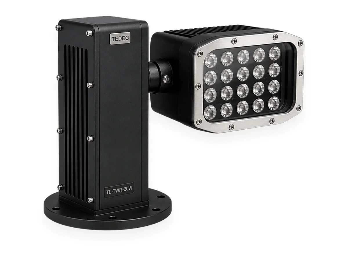
Turret-roof space is where clashes most often appear: the T-Light TWR military searchlight is designed for integration into military weapon turrets and turns with the turret in the horizontal axis. Where launcher banks share that turret, check beam and firing lines together.
Control and Firing Groups
The last layer is how the launchers are fired. On the TDG-76-SGL, all launchers are managed from a remote control unit inside the vehicle. The operator can fire launchers individually, in groups or all at once, and can switch between manual and automatic modes. The front panel carries separate fire buttons for the left group, the right group and all smoke ammunition, an ammunition indicator (present/absent), an arm/safe mode select switch and a status LED.
Grouping therefore has to be decided together with layout:
- Left and right groups: launchers covering the vehicle's left and right sectors are wired to the matching group, so the operator closes the threatened side with one button.
- All at once: screens the whole chosen sector with a single command; the emergency response.
- Individual firing: builds the screen piece by piece according to wind and threat direction, or conserves ammunition.
With CANBUS (J1939), the system communicates with the vehicle's other electronic systems over the same data bus. Which data is shared, and what the automatic mode is tied to, are settled during integration.
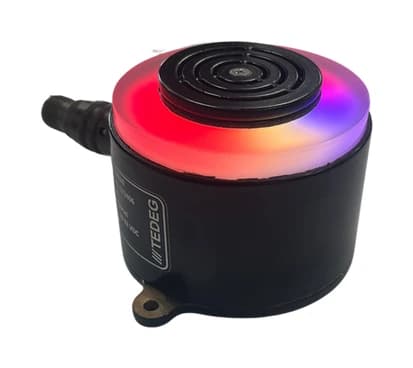
Warning personnel around the vehicle before firing is a job for a separate warning point: the T-Light Programmable Warning Unit combines audible and visual warning in a single housing, in RS-485 or CAN-Bus models.
Power Budget and Cabling
The TDG-76-SGL runs on a 28 VDC nominal (16–32 VDC) supply. The datasheet gives two consumption values at 28 VDC: 120 mA ± 20 mA nominal and 6 A ± 2 A in firing mode. This has three consequences:
- Line protection is sized for the firing current. Fuse and cable cross-section follow the current at the moment of firing, not the low standby draw. The line is fed from a fused distribution output; the TDG-EDP-D0X DC Power Distribution Unit, for example, protects its output lines with MIDI-type fuses (30, 60 and 100 A at 28 VDC).
- On a turret, power and data pass through the rotary joint. Check its spare channels and current capacity before the launcher count is frozen.
- Compliance is confirmed at system level. The TDG-76-SGL's military condition resistance is to MIL-STD-461G, MIL-STD-810G and MIL-STD-1275E. Cable shielding, grounding and routing remain part of the vehicle integration; see our MIL-STD-461 and MIL-STD-810 guide.
A Checklist for Selecting the Configuration
Eight questions to answer before requesting a quotation:
- 1.What will the vehicle do after firing: withdraw, relocate or stay in place?
- 2.Which sector must be screened: 90°, 120°, 180° or 360°?
- 3.Is a second salvo needed without reloading?
- 4.Turret or hull, and where are the mounting surfaces and nearby equipment?
- 5.Which munition types, and are cloud width and range data available?
- 6.How are firing groups split; is automatic mode required?
- 7.Do the supply line, fuse and rotary joint suit the firing current?
- 8.Which data is shared on the vehicle data bus (CANBUS J1939)?
With a top-view drawing of the vehicle, these answers usually settle the arrangement in one round.
Multiple Smoke Grenade Launcher Manufacturer in Turkey: TEDEG Defence
The TDG-76-SGL is a 76 mm multiple smoke grenade launcher system developed by Ankara-based TEDEG Defence and manufactured in Turkey.
| Fact | Detail |
|---|---|
| Manufacturer | TEDEG Defence Industry A.Ş. |
| Location | Ankara, Turkey |
| Founded | 2023 |
| Product | TDG-76-SGL 76 mm smoke grenade launcher system |
| Registrations and certificates | NCAGE TM885, ISO 9001, EYDEP |
| Cluster memberships | OSSA, SAHA Istanbul |
Datasheet values for configuration:
- Configuration range: minimum 4, maximum 16 launchers; 90°, 120°, 180° or 360° smoke coverage
- Vehicle integration: 28 VDC nominal (16–32 VDC), CANBUS (J1939); land and naval vehicles
- Environment: −40 °C … +70 °C, 95% humidity, zinc-nickel coating; MIL-STD-461G, MIL-STD-810G, MIL-STD-1275E
Certificates are on the Certifications & Quality page; searchlight, lighting and warning products are in the Tactical Systems category.
Frequently Asked Questions
How many smoke grenade launchers does an armoured vehicle need?
The count follows from the sector to be screened and whether a second salvo is needed. Typically, light vehicles use 4–8 launchers and heavy fighting vehicles 8–12. The TDG-76-SGL is fitted with a minimum of 4 and a maximum of 16 launchers, set according to the platform's needs.
How many launchers are needed for 360° coverage?
In pure geometry, 8 launchers around the full perimeter spread the axes 45° apart, 12 launchers 30° and 16 launchers 22.5°. Which spacing gives an unbroken screen depends on the cloud width of the munition, so launcher count is chosen together with the munition data.
How does a multiple smoke grenade launcher connect to the vehicle electronics?
The TDG-76-SGL is fed from a 28 VDC nominal (16–32 VDC) line and communicates with the vehicle's other electronic systems over CANBUS (J1939). Fuse and cable cross-section are chosen for the 6 A ± 2 A drawn in firing mode.
Conclusion
A multiple smoke grenade launcher configuration is four decisions made together: arc, count, layout and firing groups. The TDG-76-SGL leaves room on each: 4 to 16 launchers, 90°–360° coverage, individual, group and full firing, and CANBUS (J1939) integration. Datasheet and CAD requests are on the product page; the full range is in the product catalogue. With a top-view drawing of your platform and the checklist answers, request a quotation or use the contact page.