What Is a DC Busbar?
A DC busbar is a solid copper or tinned-copper bar, rather than a cable, that joins the sources and loads of a direct-current system at one common point. On a military vehicle the battery groups, alternator and charger connect to the positive (+) bar, the chassis return to the negative (−) bar, and the loads are fed through fused lines. The DC bus voltage between the two bars is what every piece of equipment sees.
This article covers three parts of the distribution layer defined in our military vehicle electrical architecture guide: busbar cross-section, fuse selection and cable sizing. Scope: land vehicles, shelters and fixed installations.
Why Use a Busbar in a Vehicle?
Wiring every source and load separately means a lug, a route and a protection device per connection. A busbar brings them onto one conductor:
- A shorter harness: sources and loads meet at one point.
- One protection logic: input contactors, battery isolator and emergency stop sit in front of the bar, so all distribution is cut with one action.
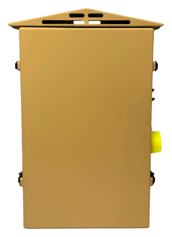
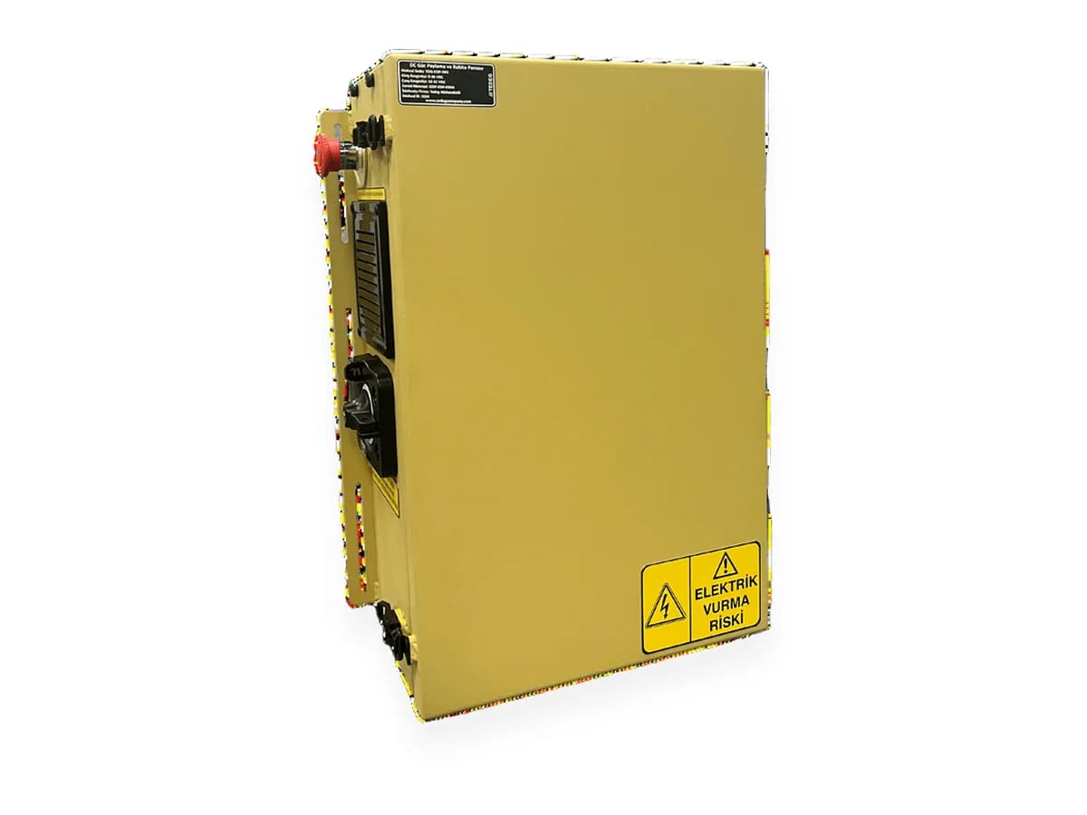
TEDEG's TDG-EDP-D0X Military Vehicle DC Power Distribution Unit is an example: according to its datasheet, four inputs (Battery 1, Battery 2, alternator and battery charger) are collected on (+) and (−) 400 A busbars, and the outputs are protected by MIDI-type fuses.
Bus Voltage: What 28 VDC Means
Bus voltage is not constant. Two 12 V battery groups in series give a nominal 24 V; under alternator charging the bus typically sits around 28 V; and it dips during engine starting. MIL-STD-1275 defines the limits of these variations for military land vehicles.
Two consequences: cable and fuse calculations use the lowest bus voltage, where current for a given power is highest. And the contactors on the bar work on voltage thresholds: on the TDG-EDP-D0X the input contactor closes above 21.5 VDC and opens below 21 VDC, disconnecting the batteries; all thresholds except the control unit's switch-on voltages are adjustable.
How Is Busbar Cross-Section Determined?
Three questions set the cross-section:
- 1.Continuous current: The bar must carry the larger of the two: the sum of all output lines in normal operation, or the maximum current the sources can deliver.
- 2.Peak current: When starting, turret drive or a heater coincide, does the bar temperature stay within limits?
- 3.Temperature rise: In a closed panel at ambients such as −32 °C to +52 °C, does the bar's self-heating affect the fuses and cable insulation at the joints?
A copper bar's capacity depends on its area, cooling surface and permitted temperature rise. The practical rule: size the bar for the real simultaneous current of sources and loads, not for the sum of the fuses that could be fitted. On the TDG-EDP-D0X that value is 400 A.
The Fuse Protects the Cable, Not the Load
The most common mistake is to assume the fuse protects the load. It protects the cable and its connections from fire; the semiconductors of an electronic load fail long before it opens. The rating is chosen between two limits: above the continuous load current (typically a 25–30% margin against nuisance tripping) and below the cable's ampacity.
Two DC-specific points:
- Arc extinction: DC has no zero crossing, so the arc does not self-extinguish; the fuse's DC voltage rating and breaking capacity must suit the prospective short-circuit current at the installation point.
- Time-current curve: fast fuses for semiconductor loads, time-delay fuses for motors and contactors with high inrush.
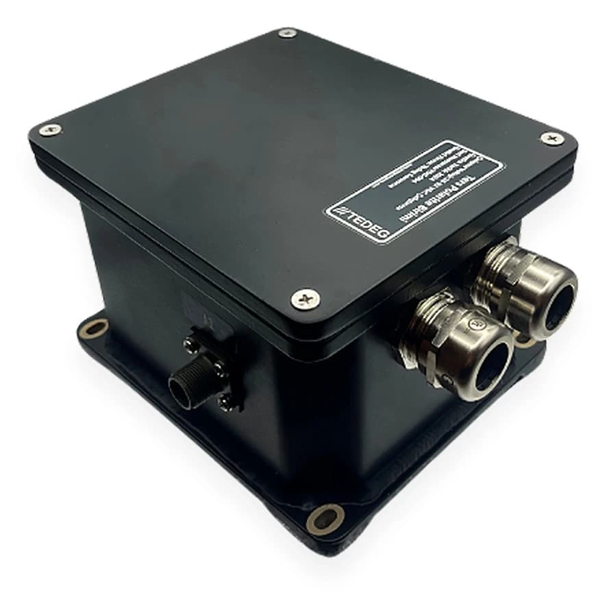
The TDG-EDP-D0X uses MIDI-type fuses on its outputs, 30, 60 and 100 A @28 VDC, and carries three spares in each of the 30, 60, 100 and 200 A ratings. Protecting the battery line against reverse connection is not a fuse's job; see our reverse polarity guide and the TPB-01 Reverse Polarity Unit, rated for currents up to 500 A.
Cable Cross-Section: Ampacity and Voltage Drop
Cable cross-section is checked against two criteria; the larger result is used.
Ampacity is read from the manufacturer's table for the insulation class, derated for hot locations such as the engine bay, bundled conductors and closed ducts. Military vehicle cables are usually specified by AWG size; the TDG-EDP-D0X datasheet calls for "AWG military cables sized to the power requirement".
Voltage drop is calculated with:
A = 2 × ρ × L × I / ΔV
with A the cross-section (mm²), ρ copper resistivity (about 0.0175 Ω·mm²/m), L the one-way length (m), I the current (A), ΔV the permitted drop (V); the 2 counts both conductors. On a 28 VDC bus a 2% budget is 0.56 V; for a 10 A camera group 5 m away, A ≈ 2 × 0.0175 × 5 × 10 / 0.56 ≈ 3.1 mm², and the next standard size up is selected.
Sizing the Three Together
Calculate from the load towards the bar:
| Step | Input | Output |
|---|---|---|
| 1 | Continuous and peak load current, cable length | Cable cross-section (larger of ampacity and voltage drop) |
| 2 | Cable cross-section, load type | Fuse rating and curve (above the load, below the cable) |
| 3 | Simultaneous current of all lines, source current | Busbar cross-section, input contactor rating |
| 4 | Mounting location, ambient temperature | Derating, cooling, spare fuse plan |
The same order applies to AC. According to its datasheet, TEDEG's PowerGuard MAR-2 Power Distribution Panel splits a 220 VAC 50 Hz mains or generator source into 9 independently fused 220 VAC outputs, each with its own neutral and earth terminal and cable cross-sections matched to the load. Per-channel protection in rack-mount PDUs is covered in our military PDU guide; all distribution products are listed under Power Distribution Units (PDU).
Frequently Asked Questions
Is the fuse rating chosen from the load current or the cable current?
Both: above the continuous load current and below the cable ampacity. If the two collide, enlarge the cable, not the fuse.
Can an AC fuse be used on a DC busbar?
Only if the manufacturer states a DC voltage rating and breaking capacity; a fuse labelled only for AC may fail to open under a DC short circuit.
Is the bus voltage 24 V or 28 V?
Nominally 24 V at the battery, typically around 28 V under alternator charging; standards and datasheets therefore say 28 VDC, while cable and fuse calculations use the lowest bus voltage.
Conclusion
The DC busbar is the collection point of the vehicle's electrical architecture: the bar follows the real simultaneous current, the fuses protect the cables, and the cables follow the larger of ampacity and voltage drop. Sized separately, they produce nuisance trips or hot joints in the field.
For a busbar, fuse and cable plan for your vehicle, request a quote or contact our engineering team.
Field example: Read the tactical truck power architecture case study.