What Are CAN Bus and SAE J1939 in Military Vehicles?
On a military land vehicle the video management unit, warning units, seat monitoring, smoke launcher control and engine electronics share one data bus. That bus is usually CAN, and the language on it is often SAE J1939. The most common confusion in military vehicle CAN bus integration sits here: CAN is a transport layer, while J1939 defines how messages are named, who sent them and how faults are reported.
Most J1939 explanations are written for commercial trucks. On a military vehicle the protocol lives with 28 VDC transients, a harsh electromagnetic environment, blackout discipline and platform-specific interface documents. This guide covers protocol basics, bus design and specification questions from that angle. For the data layer's place in the wider architecture, see what is vetronics.
CAN vs J1939: the Road and the Language
CAN (Controller Area Network) is a physical and data-link layer defined in ISO 11898: a two-wire differential bus, bit timing, arbitration and error detection. It does not say what a message means; it carries an 11-bit or 29-bit identifier and up to 8 bytes of data.
SAE J1939 gives that identifier meaning: which message carries engine speed, how a device obtains an address, how data longer than 8 bytes is split and how fault codes are broadcast.
| Layer | CAN (ISO 11898) | SAE J1939 |
|---|---|---|
| Physical bus | Differential pair (CAN_H / CAN_L), termination | J1939-11 / -14 / -15: cable, bit rate, bus length |
| Identifier | 11-bit (CAN 2.0A) or 29-bit (CAN 2.0B) | 29-bit only; priority, PGN and source address fields |
| Data | Up to 8 bytes | Parameter (SPN) definitions, scaling and units |
| Network management | Not defined | Address claim |
| Diagnostics | Bus error counters only | Diagnostic messages such as DM1 |
In practice, a datasheet that says "CAN bus" may only promise the physical layer; "J1939" defines the upper layer too. The interface control document (ICD) closes the gap.
How to Read the J1939 29-Bit Identifier
J1939 splits the 29-bit CAN 2.0B identifier into fields:
| Field | Bits | Role |
|---|---|---|
| Priority | 3 | 0 is highest, 7 is lowest priority |
| EDP / DP | 1 + 1 | Data page selection |
| PDU Format (PF) | 8 | Message type; below 240 is destination-specific, 240 or above is broadcast |
| PDU Specific (PS) | 8 | Destination address or group extension |
| Source address (SA) | 8 | Device that sent the message |
Because priority sits at the front of the identifier, it decides arbitration: the lower value wins and the other node retries without losing data. Ranking safety messages above periodic status data is therefore a design decision.
PGN, SPN and Source Address
EDP, DP, PF and PS together form the 18-bit PGN (Parameter Group Number), which names a group of parameters; each parameter is an SPN (Suspect Parameter Number). Engine speed, for example, is carried as SPN 190 inside PGN 61444 (EEC1). Source addresses run 0–253; 254 is "null", 255 is "global".
Address Claim, Long Messages and Diagnostics
Each J1939 device claims an address at power-up with a 64-bit NAME (PGN 60928); if two want the same address, the higher-priority NAME wins. Where a vehicle carries two units of the same type, the ICD should say whether addresses are fixed or claimed.
Data longer than 8 bytes uses the transport protocol, up to 1,785 bytes. For faults the key message is DM1 (PGN 65226), which periodically broadcasts active fault codes as SPN and failure mode identifier (FMI) pairs.
Where J1939 Is Used on a Military Vehicle, and Where Custom Protocols Are
Coming from heavy trucks, J1939 is close to standard on the engine, transmission and brakes. The mission side is mixed: some platforms extend J1939 to mission messages, some run a programme-specific protocol over CAN, and some use CAN-based military definitions such as MilCAN. A subsystem supplier must therefore be able to define its message list in the ICD to match the platform's chosen protocol.
TEDEG datasheets show these levels:
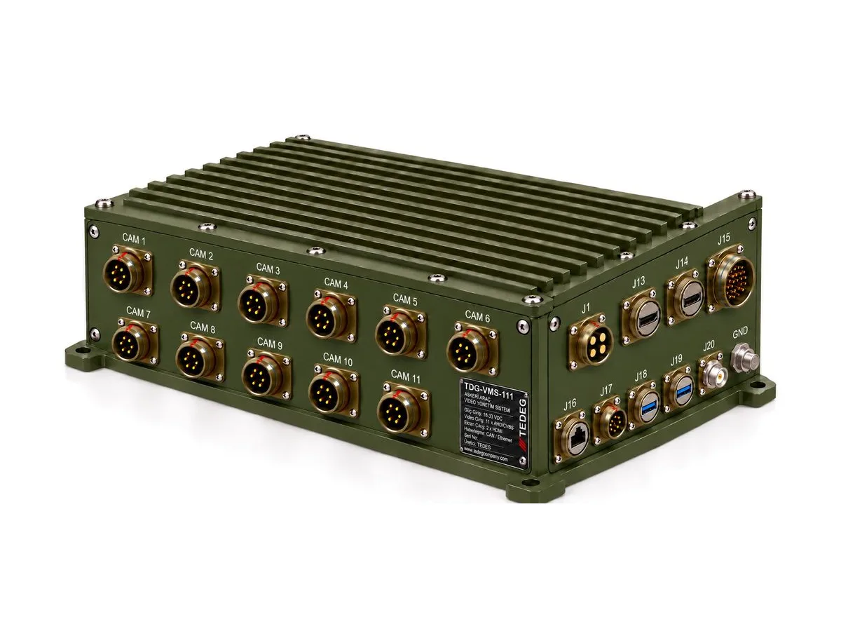
- The military vehicle video management system TDG-VMS-111 has 2 × CAN 2.0B (J1939 / custom) and 2 × RS-422/485 on its vehicle interface. Views switch on reverse gear, indicators, a speed threshold and door/ramp signals (CAN or discrete inputs), and the optional TDG-VMS-KP panel connects over CAN + 12 VDC. These are Rev. 01 preliminary design values.
- The 76 mm smoke grenade launcher system TDG-76-SGL lists its communication as CANBUS (J1939); its remote control unit has a CAN-Bus infrastructure and shares the bus with the vehicle's other electronic systems.
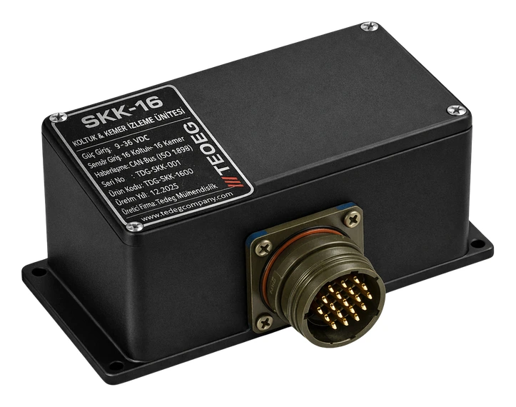
- The military seat belt monitoring system SENTRA-16 sends its data to the mission computer over CAN-Bus (ISO 11898, 500 kbps). The datasheet gives the physical layer and bit rate; the upper-layer protocol and identifiers are agreed in the ICD before order. See our guide to seat and seat-belt monitoring.
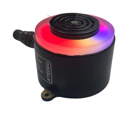
- The programmable warning unit T-Light is made as two separate models, RS-485 or CAN-Bus; the protocol is chosen at order and cannot be changed in the field. Connection status and the last received command can be queried over the bus.
Unless bit rate, identifier length, protocol and message list are written down together, two devices can share a bus and still not understand each other. These products are in the military vetronics and tactical systems categories.
Bus Topology and Termination
A CAN bus is a linear backbone, not a star: devices join through short stubs and each end carries a 120 Ω termination resistor. With power off, CAN_H to CAN_L should read about 60 Ω; 120 Ω means one resistor is missing, around 40 Ω points to an extra one. Either way the result is reflections, rising error counters and intermittent communication loss.
J1939-11 defines a 40 m backbone with shielded twisted pair at 250 kbps, up to 30 nodes and stubs of up to 1 m; J1939-14 adds 500 kbps and asks for shorter stubs. Draw backbone length and stub positions early; a unit added later often becomes the longest stub.
State which node carries termination; an external termination plug keeps it in place when the end unit is removed.
One Bus or Two?
Many platforms separate the chassis network from the mission network, keeping bus load manageable and stopping a mission fault from affecting driving functions. Two CAN interfaces are therefore common on mission units, with a controlled gateway between networks.
EMI and Power Measures on a Military Vehicle
CAN is differential and tolerates common-mode noise, but a military vehicle pushes that tolerance hard:
- Cable and screen: Twisted pair, screened cable and a 360° screen termination at the connector are the first defence; whether the screen is grounded at one end or both follows the platform grounding plan.
- Common mode and isolation: Chassis potential can differ between remote units; if transceiver common-mode range is exceeded, data is corrupted. Galvanic isolation reduces that risk.
- Power transients: Cranking dips and surges on the 28 VDC network can reset a unit with a weak supply stage; it repeats address claim and vanishes from the bus for a while. See our MIL-STD-1275 guide.
- Bus-off behaviour: A node whose error counter passes a threshold leaves the bus. Recovery should be written into the ICD, or one noise event can silence a subsystem for the rest of the mission.
- Verification: Susceptibility is assessed with MIL-STD-461 tests such as CS114 and RS103; see our MIL-STD-461 and MIL-STD-810 guide.
Blackout is a bus topic too: the command should reach warning units, displays and indicator panels in one message, with a defined default if it is lost. T-Light's blackout mode switches off its LEDs and audible alerts completely; the message carrying that command belongs in the ICD.
Questions for the Specification and the ICD
| Topic | Question to ask |
|---|---|
| Physical layer | ISO 11898 transceiver type, bit rate (250 / 500 kbps), isolation? |
| Protocol | J1939 or programme-specific? 29-bit or 11-bit? |
| Message list | PGN / SPN or identifier list, period, priority, scaling and units |
| Addressing | Fixed address or address claim? NAME fields |
| Diagnostics | DM1 or equivalent; list of fault codes |
| Termination | Internal or external? At which node? |
| Connector and pins | CAN_H, CAN_L, CAN GND and screen pins |
| Fault behaviour | Recovery after bus-off, default state on loss of communication |
| Bus load | Load calculated with all messages, and its upper limit |
For example, T-Light's PT02E-10-6P connector defines pin C as CAN_H, pin D as CAN_L and pin E as CAN-Bus GND; freeze such details in the ICD before the harness drawing. For interface definition and integration support, see our system integration service.
Frequently Asked Questions
Are CAN bus and J1939 the same thing?
No. CAN bus (ISO 11898) is the physical and data-link layer; SAE J1939 is the upper-layer protocol that gives the 29-bit identifier meaning and adds addressing, long-message and diagnostic rules.
What bit rate does J1939 use?
Classic J1939 runs at 250 kbps (J1939-11, J1939-15); J1939-14 adds 500 kbps. All nodes on a bus share one bit rate.
How do you check the termination on a CAN bus?
With power off, measure between CAN_H and CAN_L. About 60 Ω is correct (two 120 Ω in parallel); about 120 Ω means one is missing; clearly below 60 Ω means extra termination.
If a device says "CAN bus", does it speak J1939?
Not necessarily. "CAN bus" often describes only the physical layer. Whether the device sends J1939 or programme-specific messages, and which PGNs and address it uses, should be stated in the datasheet or ICD.
Conclusion
Set up properly, CAN bus and SAE J1939 let a military vehicle's subsystems speak one language; set up poorly, the problem appears in the field as intermittent communication loss. Writing bit rate, protocol, message list, termination and fault behaviour into the ICD early prevents most harness and test surprises.
Share your platform's data bus details and subsystems through our quote form, or send technical questions via the contact page.