What Is Vetronics?
Vetronics is short for "vehicle electronics": the power, data, vision, display and control electronics integrated into a military vehicle. The short answer to "what is vetronics" is this: everything electronic on the platform beyond the engine and the armour that lets the crew see, communicate and manage the vehicle and its mission systems, together with the architecture that ties those subsystems to one another.
This guide opens the concept up layer by layer: which subsystems belong to vetronics, how they connect on the power and data sides, what the open-architecture standards govern and what to look for in a specification. The power side in detail, from batteries and alternator to busbar and distribution, is covered in our military vehicle electrical architecture guide; the two articles are two faces of the same vehicle. A short definition is in the glossary, and the products are listed under military vetronics.
Which Subsystems Does Vetronics Cover?
The boundary of the term shifts with the platform and the programme, but on a tactical wheeled or armoured vehicle the following subsystem groups are usually counted under vetronics:
| Subsystem group | What it does | Typical components |
|---|---|---|
| Power distribution and conversion | Delivers 28 VDC vehicle power to the subsystems, protected and, where needed, isolated | Power distribution unit, supply modules, DC-DC converters, inverters |
| Vehicle data bus and communications | Carries status and command data between subsystems | CAN bus (J1939), RS-485 / RS-422, Ethernet, radio and intercom interfaces |
| Vision and situational awareness | Shows the driver and commander the vehicle's surroundings | Driving and surround cameras, night-vision cameras, video management unit |
| Human-machine interface | Lets the crew see the systems and issue commands | Operator displays, control panels, mission computer |
| Crew safety | Monitors personnel status and raises alerts | Seat and belt monitoring, door / ramp signals, audible-visual warning units |
| External lighting and warning | Illuminates the surroundings, signals status and goes fully dark on command | Searchlights, warning units, blackout switches |
| Mission and self-protection systems | Performs the platform's mission-specific functions | Smoke launcher control, turret interfaces, sensor units |
These groups are not independent of each other. A camera is both a load on the power layer and a source on the data layer; a warning unit takes its commands from the vehicle bus and, in blackout mode, follows the external lighting discipline. That is why vetronics is easier to reason about as layers rather than as a list of boxes.
The Five Layers of a Vetronics Architecture
1. Power Layer: 28 VDC and Isolation
Most military land vehicles run on a nominal 28 VDC network, whose steady-state range and transients are defined by MIL-STD-1275. From a vetronics point of view, the job of the power layer is to deliver that network to every subsystem at the right voltage, protected and, wherever possible, through isolated outputs. Isolation matters for two reasons: ground loops circulating through the vehicle chassis inject noise into analogue video and audio lines, and without isolation a short circuit on one channel pulls down the voltage on the others.
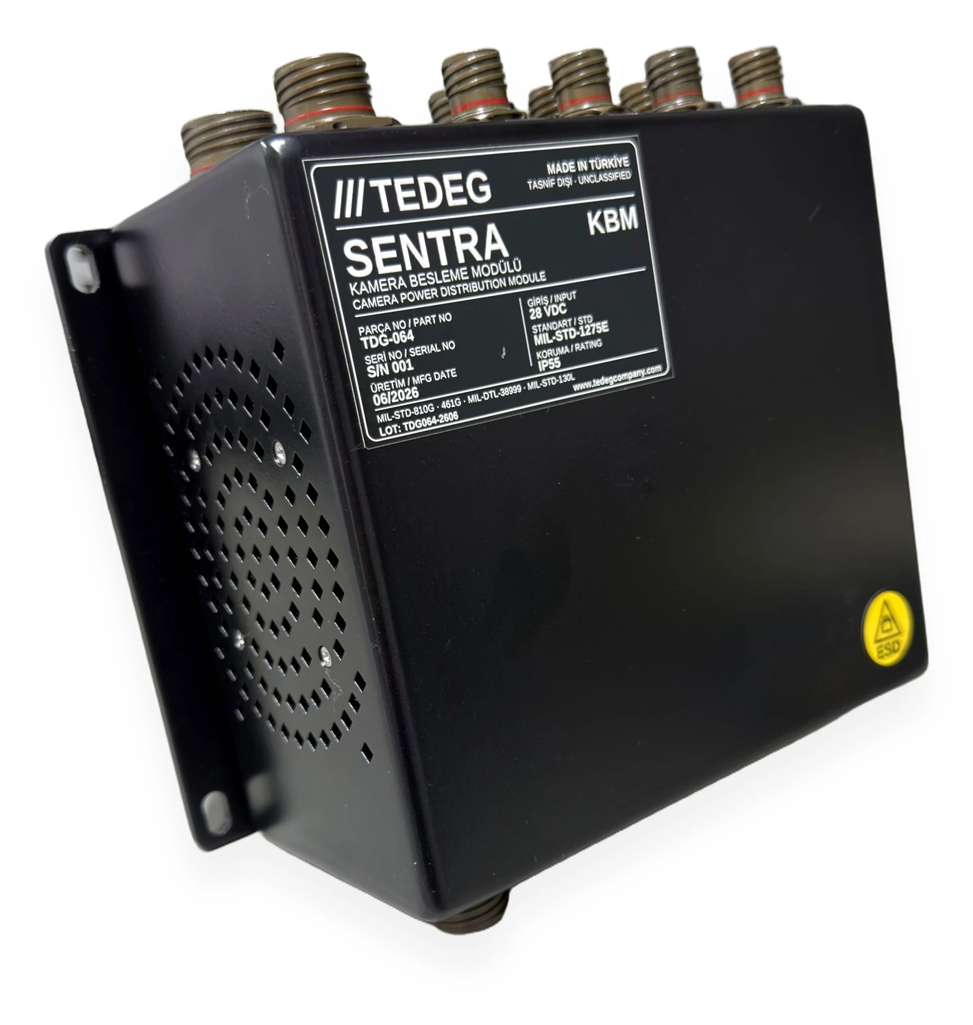
One example of this layer is the military camera power distribution module SENTRA KBM. According to its datasheet the input is a 28 VDC military vehicle electrical system compliant with MIL-STD-1275E; on the output side there are at least 11 isolated 12 VDC camera outputs, a 24 VDC ±0.2 V mission computer output (min. 200 W), an isolated 24 VDC display output (min. 25 W) and a separate seat module output. All connections use MIL-DTL-38999 connectors. The design details of camera power, ground loops and harness layout are covered in our guide on how to power armoured vehicle cameras.
2. Data Layer: CAN Bus, J1939 and Ethernet
Status and command data between subsystems travels on the vehicle data bus. On land vehicles the most common backbone is CAN bus (ISO 11898); at the upper layer most platforms use the SAE J1939 protocol or a programme-specific CAN protocol. Gigabit Ethernet has become common for video and mission data that need high bandwidth, while RS-485 and RS-422 are still used for control panels and simple sub-units.
The data layer is what turns vetronics from a pile of individual devices into a system. A few examples:
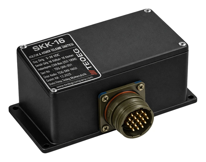
- The military seat and belt monitoring system SENTRA-16 reads 32 channels (16 seats + 16 belts) and sends the data to the vehicle mission computer over CAN bus (ISO 11898, 500 kbps).
- The military vehicle video management system TDG-VMS-111 has 2 × CAN 2.0B (J1939) and 2 × RS-422/485 on its vehicle interface; views switch automatically on vehicle signals such as reverse gear, indicators and speed, and video reaches the mission computer as an RTSP / ONVIF stream over Gigabit Ethernet. The datasheet gives these as Rev. 01 preliminary design values.
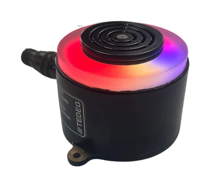
- The programmable warning unit T-Light is built as two separate models, one communicating over RS-485 and one over CAN bus; the protocol is specified at the time of ordering.
- The remote control unit of the 76 mm smoke grenade launcher system TDG-76-SGL communicates with the vehicle's other electronic systems over the same data bus thanks to its CANBUS (J1939) infrastructure.
Bus topology, termination and cable screening are frequent sources of error in vetronics integration; we will cover CAN bus and J1939 for military vehicles in a separate guide.
3. Vision and Situational Awareness Layer
Closed-hatch driving, manoeuvring in confined spaces and night movement require the driver and commander to see, through cameras, the areas they cannot see directly. This layer consists of the cameras, the video management unit and the image-processing functions. The design questions are: how many cameras, in which format (analogue AHD / CVBS or IP), where the images are processed (a dedicated video management unit or the mission computer), what latency is acceptable and whether recording is needed.
The TDG-VMS-111 datasheet gives a concrete example for this layer: 11 independent AHD / CVBS camera inputs, a real-time 360° bird's-eye view stitched from four wide-angle cameras, 2 × HDMI display outputs and camera-to-display latency below 80 ms in a single view. The unit runs from 18–33 VDC (28 VDC nominal) and its input is designed to MIL-STD-1275E power quality; the values are Rev. 01 preliminary design values. The cameras themselves are in the military vehicle camera systems category.
4. Human-Machine Interface: Displays and Controls
The crew sees and manages the subsystems through displays, control panels and mission computer software. The properties sought in a military vehicle display are sunlight readability, a touch surface that works with gloves, a backlight option compatible with night-vision goggles and military connectors.
In the vehicle vision chain, the HDMI outputs of TDG-VMS-111 drive the 10.1" TDG-DSP-101 display, which runs from 9–36 VDC and takes HDMI on a MIL-DTL-38999 type circular connector. The display is supplied and integrated as part of the vehicle vision package. The real engineering work in this layer is the view logic: which camera is shown when, and how the blackout command affects the backlight.
5. Crew Safety, Warning and Blackout
The fifth layer monitors the state of the personnel and signals status to the vehicle or its surroundings. Seat occupancy and seat-belt monitoring, door and ramp status, audible-visual warning and blackout mode all belong here. Two design principles stand out: warning behaviour should be defined in software rather than hardware, so that the same unit fits different scenarios on different platforms, and blackout must be enforceable with a single command across the whole system.
The T-Light warning unit datasheet reflects these principles: colour, flashing and sound level change with commands from the control system; the audible alert is a maximum of 110 dB in three levels; blackout mode switches off the LEDs and audible alerts completely. The unit runs from 16–32 VDC, has an IP68 housing, and its datasheet gives MIL-STD-810H 514.8 vibration and 516.8 shock values. SENTRA-16 runs from 18–32 VDC, draws less than 15 W and has an IP65 enclosure.
Why Power and Data Are Designed Together
The most common mistake in a vetronics architecture is to have one team design the power distribution and another design the data bus, independently of each other. The two layers affect each other directly:
- Ground loops: If the power going to a camera and the video coming back take their chassis reference from different points, noise rides on the analogue video line. The fix is in the power layer (an isolated output); the symptom shows up in the data and vision layers.
- Emitted disturbance: A switch-mode power supply or the siren driver of a warning unit can raise the error counter on the CAN line through the ripple it feeds back onto the vehicle bus. This is why MIL-STD-1275 also limits the disturbance emitted by equipment and why MIL-STD-461 measures conducted emissions; the relationship between the two standards is explained in our MIL-STD-461 and MIL-STD-810 guide.
- Blackout: Blackout is a system behaviour, not a feature of one device. The warning unit's LEDs, the display backlight and the status indicators of the power panel must go dark on the same command or the same switch. For example, the BLACKOUT switch on the front panel of the military power conversion unit TPS-24DCAC extinguishes only the indicators while the power lines remain live; the same blackout command has to reach the warning unit over the data bus.
- Start-up sequence: Unless it is planned jointly which subsystem is energised first at ignition and when it reports "ready" on the bus, the display comes up with no camera image.
The loads on the tactical systems side, the turret-mounted searchlight (16–33 VDC) and the warning unit, are in the tactical systems category; how those loads share the vehicle bus with the power distribution and the cameras is covered in the architecture guide.
Open Architecture Standards: NGVA, GVA and VICTORY
Historically, vetronics was a closed field in which every subsystem supplier brought its own display, its own cabling and its own protocol. The result was a growing number of screens inside the vehicle, a heavier harness and an integration redone with every upgrade. Open architecture standards were developed against that problem:
- NGVA (NATO Generic Vehicle Architecture, STANAG 4754): the common definition of the electronic infrastructure, data model and interfaces for NATO land vehicles. It aims to have subsystems talk over an Ethernet-based vehicle network using a shared data model.
- GVA (Generic Vehicle Architecture, DEF STAN 23-09): the approach developed in the United Kingdom that formed the basis of NGVA, with common rules for power, data and the human-machine interface.
- VICTORY: the US Army architecture that aims to bring in-vehicle electronics together on a common network and to distribute position, navigation and timing data to every device.
These standards are used to write a platform's integration rules, not to declare a product "compliant". A subsystem supplier is expected to define in the ICD the interfaces (data model, physical layer, power interface) that match the architecture the platform has chosen. The datasheets of the TEDEG products mentioned in this article make no claim of compliance with these architectures; the interfaces are finalised for the platform through a pre-order ICD.
Common Problems in Vetronics Integration
Field experience shows that most problems in vetronics programmes arise at the interfaces rather than in the individual devices:
- 1.An undefined ICD: The harness is built before pin assignments, connector types and data messages have been frozen in writing; every pin that changes later means a harness revision.
- 2.No power budget: Camera, display, computer and warning loads each look small; added together, with inrush currents included, they exceed the channel capacity of the distribution unit.
- 3.No grounding plan: Without a single written grounding plan for chassis-referenced sensors, isolated camera outputs and screened video lines, the noise problems are found in the field.
- 4.Bus termination: With no termination resistor at the two ends of the CAN line, or with an extra third one, the error counter climbs; the symptom is intermittent loss of communication.
- 5.Scope of environmental qualification: Which unit has been verified with which MIL-STD-810 methods, and at which levels, is not asked at the quotation stage; the gap surfaces at acceptance testing.
Each of these can be prevented by an interface control document written at the start of the programme and disciplined system integration work.
What to Look For in a Vetronics Specification
When writing a specification for a subsystem or for a complete vetronics package, the following headings form the minimum list:
| Heading | Question the specification should answer |
|---|---|
| Power input | Nominal voltage and range; MIL-STD-1275 revision; reverse polarity and over-voltage protection; isolated output requirement |
| Data interface | Protocol (CAN 2.0B / J1939, RS-485, Ethernet); message list; speed; responsibility for termination |
| Connector | Family (MIL-DTL-38999 etc.), shell size, contact arrangement, plating |
| Environmental | Temperature range; IP rating; vibration and shock methods and levels |
| EMI / EMC | MIL-STD-461 revision and the tests to be applied (CE102, RE102, CS114 etc.) |
| Level of evidence | Design declaration or qualification report; if a report is required, its scope |
| Blackout and night compatibility | Blackout command; backlight requirement compatible with night-vision goggles |
| Documents | ICD, 3D CAD / STEP, operation and maintenance manual, configuration control |
"Designed to" and "tested to" are different levels of evidence; the specification should state clearly which one it wants.
Vetronics Manufacturer in Turkey: TEDEG Defence
TEDEG Defence is a military power electronics and vehicle electronics manufacturer based in Ankara. Its vetronics product family covers the power, data and crew safety layers:
| Company profile | |
|---|---|
| Company | TEDEG Defence Industry A.Ş. |
| Headquarters | Ankara |
| Founded | 2023 |
| Registrations and certificates | ISO 9001, EYDEP |
| Cluster membership | SAHA İstanbul |
- SENTRA KBM camera power distribution module: 28 VDC MIL-STD-1275E compliant input; at least 11 isolated 12 VDC camera outputs; 24 VDC mission computer (min. 200 W), display (min. 25 W) and seat module outputs; ≥ IP55; MIL-STD-810G CHG-1 environmental and MIL-STD-461G EMI tests specified in its datasheet.
- SENTRA-16 seat and seat-belt monitoring system: 32 channels (16 seats + 16 belts); CAN bus ISO 11898, 500 kbps; 18–32 VDC; consumption below 15 W; IP65.
- TDG-VMS-111 vehicle video management system: 11 AHD / CVBS camera inputs, 360° bird's-eye view, 2 × HDMI, 2 × CAN 2.0B (J1939), Gigabit Ethernet; 18–33 VDC MIL-STD-1275E; IP67 (Rev. 01 preliminary design values).
- T-Light programmable warning unit: max. 110 dB, multi-colour LEDs, RS-485 or CAN bus, blackout mode, 16–32 VDC, IP68.
Configuration, pin assignments and harness interfaces are finalised for the platform through a pre-order ICD. The end-to-end package of camera power, video management and display is presented in the vehicle vision section of the product catalogue; certificates are on the Certifications & Quality page.
Frequently Asked Questions
Is vetronics the same as the vehicle electrical system?
No. The vehicle electrical system is the energy infrastructure of batteries, alternator, busbar and distribution. Vetronics describes the electronic subsystems that infrastructure feeds and the data architecture that connects them. The two overlap: the power layer is the first layer of vetronics, but vetronics is not only power.
Which vehicles have vetronics?
Every military land vehicle that carries electronic subsystems, from tactical wheeled vehicles and armoured personnel carriers to reconnaissance and command vehicles. On naval platforms similar functions go by different names and different standards.
Which data bus is used for vetronics?
On land vehicles the most common backbone is CAN bus, usually with SAE J1939 at the upper layer. Ethernet is common for video and high-volume mission data, and RS-485 / RS-422 for simple sub-units and control panels. Most modern vehicles have all three side by side.
Can NGVA compliance be required from a subsystem?
If the platform has chosen NGVA or a similar open architecture, the subsystem is required to provide a data model and physical interface that follow that architecture's interface rules. The requirement is defined in the ICD and the level of evidence (declaration or test) is stated in the specification.
Where does vetronics integration start?
With the interface control document. The power budget, data message list, connector and pin assignments, grounding plan and scope of environmental qualification should be frozen in writing before harness and installation design begins.
Conclusion
Vetronics is the umbrella term for a military vehicle's electronic subsystems and the power and data architecture that connects them. Thinking in layers, designing power, data, vision, interface and crew safety separately but as connected parts, makes both the specification and the integration easier. How the camera, power and display chain was built on a tactical vehicle with a single power module is shown as an example from the field.
Share your platform's vetronics needs, camera count, number of seats to monitor and data bus details through the quote form, or reach our engineering team through the contact page for technical questions.