Why Does an Armoured Vehicle Camera System Need Its Own Supply?
An armoured vehicle camera system combines surround-view, rear-view, driver and cabin cameras, and most of them run on 12 VDC. The vehicle network is 28 VDC and carries the surges, spikes and cranking dips defined by MIL-STD-1275. Getting armored vehicle camera power right means a dedicated stage between the two: a camera power module that adapts the bus, gives every camera an isolated 12 VDC supply and stops a fault on one camera from spreading.
This article covers load budget, isolation, channel protection, transients and harness for engineers and buyers. The overall power architecture is in our military vehicle electrical architecture guide; here we focus on vehicle camera power distribution.
The Camera Load: Low Current, Many Lines
A single camera is a small load. The TDG-CAM-204 starlight rear-view camera draws about 100 mA at 12 VDC according to its datasheet. The challenge is the line count: eleven cameras mean eleven supply and eleven video lines, often plus IR control and audio. Fused individually from the busbar, they inflate the harness.
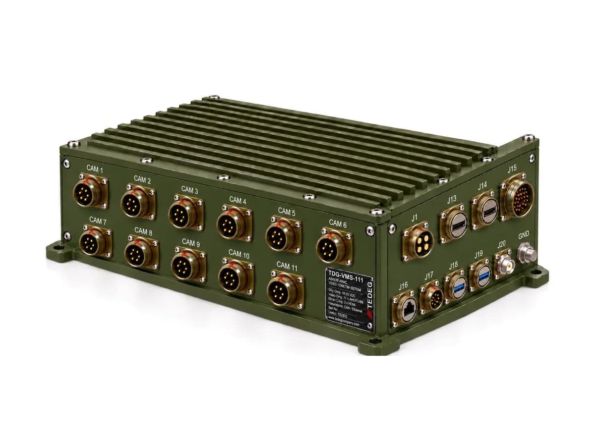
Budget for the worst case: IR cameras can draw more at night, and heated lenses need a cold-start allowance. A per-channel ceiling is practical. The TDG-VMS-111 vehicle video management system datasheet does exactly that: each channel delivers isolated 12 VDC at 0.5 A, and the camera supply of up to 11 × 6 W = 66 W is listed separately from the unit's own consumption.
Why Isolation?
Ground Loops and Analogue Video
AHD and CVBS video use the coax shield as their reference. When the camera is grounded at one end of the vehicle and the display or recorder at the other, the potential difference drives current along the shield. The result is noise, rolling bars or flicker, often worst when the turret drive or air conditioning switches on. A galvanically isolated camera supply breaks that DC path and keeps the video reference at one point.
Keeping Bus Disturbances Away
An isolated output does not pass 28 VDC bus surges and spikes straight to the camera. A small sealed camera's input stage is generally not sized for them, so protection belongs on the supply side.
Per-Channel Protection
If water shorts one camera connector, only that camera should go dark. That needs a current limit per channel; one shared fuse loses the whole view. Check whether "short-circuit and over-current protected" applies per channel or to the total output. On TDG-VMS-111, protection is per channel and each channel can be switched individually, so a faulty camera can be disabled in the field.
Voltage Transients: MIL-STD-1275E
The 28 VDC bus carries load-dump surges, spikes from switching inductive loads and dips during cranking. Their limits are defined in the applicable MIL-STD-1275 revision; the numbers are covered in the architecture guide. A camera power module's input stage should be designed for these events and state the revision letter.
Reversed battery connection is covered in our reverse polarity guide. EMI matters too, because a switching supply sits right next to the video lines. Ask which MIL-STD-461 tests define the module's emissions; our MIL-STD-461 and MIL-STD-810 guide explains them.
Harness Design: Power and Video in One Bundle
Carrying supply, video, audio and IR control on one connector per camera reduces installation and maintenance errors. Analogue video lines need cable matching their 75 Ω characteristic impedance.
Voltage drop on the 12 VDC line matters. Example: 0.5 mm² copper, 15 m one way, 0.5 A. Round-trip resistance is about 2 × 15 × 0.0175 / 0.5 ≈ 1.05 Ω and the drop about 0.5 V, roughly 4% of 12 V. On long runs, increase the cross-section or move the supply closer.
Two Architectures: Dedicated Module or Power from the VMS?
Cameras are fed either by a power module independent of video processing or by a video management system (VMS) through its own channels.
| Criterion | Dedicated power module | Power from the VMS |
|---|---|---|
| TEDEG example | SENTRA KBM | TDG-VMS-111 |
| Camera outputs | At least 11 × 12 VDC, each isolated | 11 channels, isolated 12 VDC, 0.5 A each |
| Other loads | Mission computer 24 VDC ±0.2 V, min. 200 W; isolated display output, min. 25 W; isolated seat module output | Cameras only; the unit runs on 18–33 VDC |
| Video | Single harness, min. 12 × 75 Ω lines | Processed in the unit and sent to displays |
| Best fit | Video processing elsewhere; computer and display fed from one point | Cameras, processing and camera power in one box |
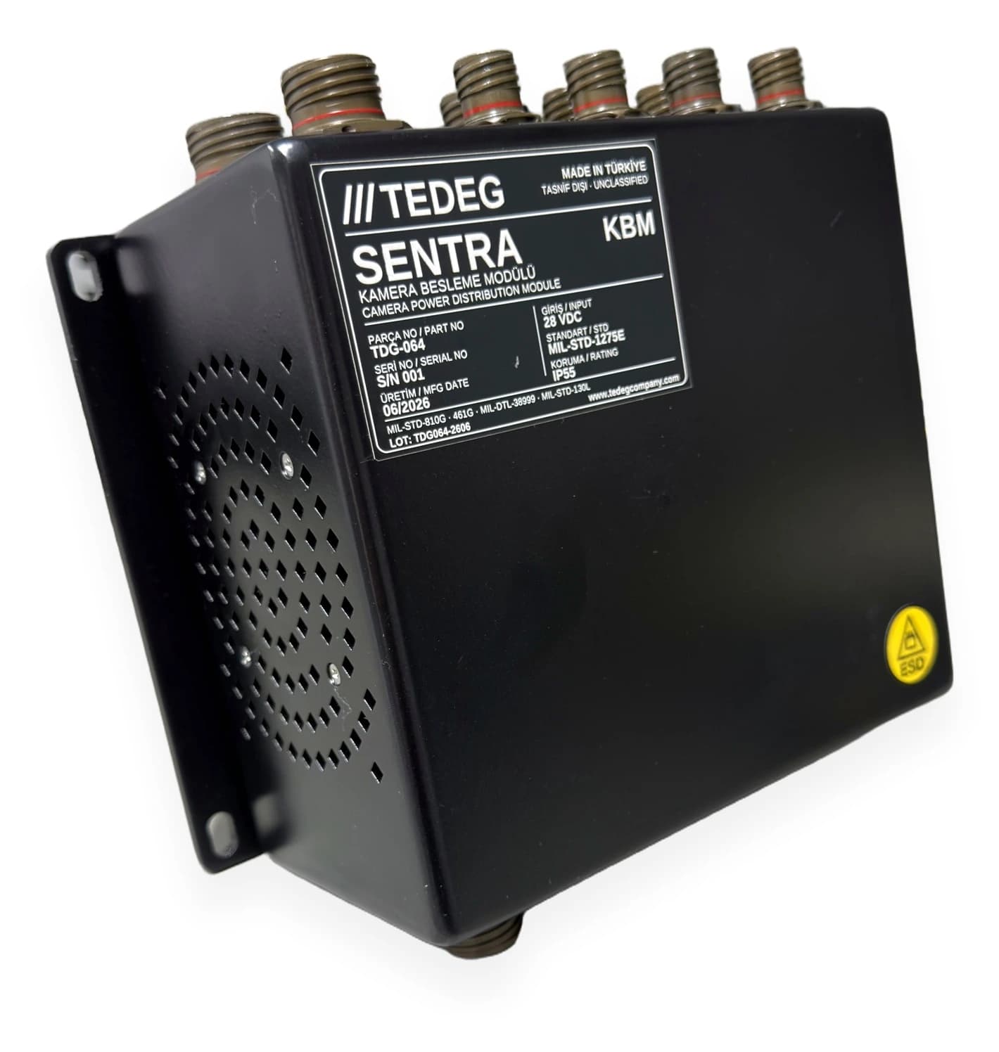
Per its datasheet, SENTRA KBM has a MIL-STD-1275E compliant 28 VDC input with reverse polarity protection and galvanic isolation; each camera gets V+, GND, video, audio and IR control on its own D38999/24WA35PN connector. CE102, CS101/114/115/116, RE102 and RS103 tests are specified under MIL-STD-461G; the enclosure is ≥ IP55 and operating temperature −32 °C to +55 °C. TDG-VMS-111 figures are Rev. 01 preliminary design values.
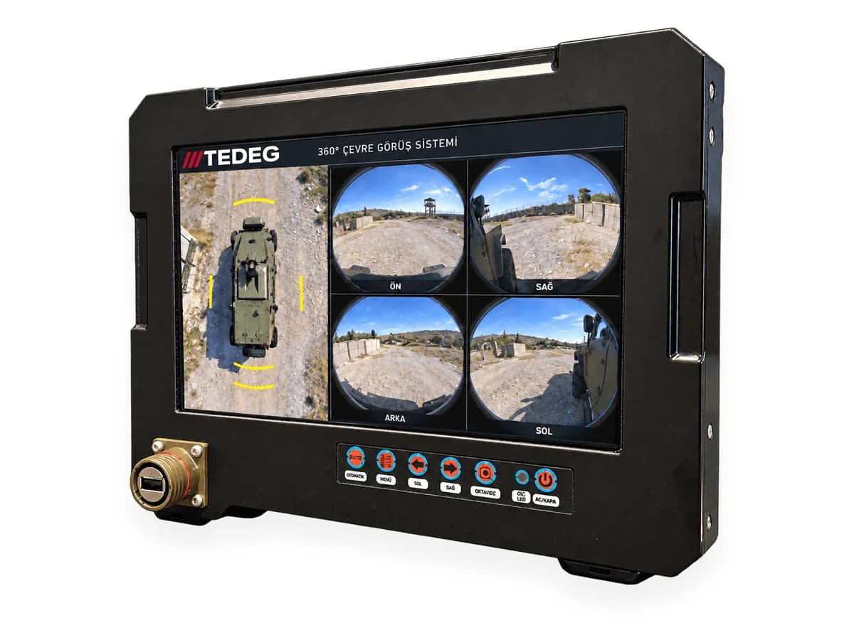
Displays are usually fed separately. The TDG-DSP-101 rugged vehicle display accepts 9–36 VDC and draws no more than 20 W; an -R variant adds a MIL-STD-1275E input stage.
7 Checks When Selecting a Camera Supply
- 1.Channels and spare: Is there a free channel beyond today's cameras?
- 2.Current per channel: Is the worst case, including IR and cold start, covered?
- 3.Isolation: Is every camera output isolated, or only the input?
- 4.Protection: Is short-circuit protection per channel, and can one channel be switched off?
- 5.Input standard: Is the MIL-STD-1275 revision stated, with reverse polarity protection?
- 6.Harness: Do power and video share the connector, with pins fixed in a pre-order ICD?
- 7.Evidence: Are the MIL-STD values a test report or a design basis?
Camera Power Module Manufacturer in Turkey: TEDEG Defence
TEDEG Defence, based in Ankara, supplies camera power, video management and display products for armoured and tactical land vehicles.
| Profile | Details |
|---|---|
| Company | TEDEG Defence Industry A.Ş. |
| Headquarters | Ankara |
| Founded | 2023 |
| Registrations and certificates | NCAGE TM885, ISO 9001, EYDEP |
| Cluster memberships | OSSA, SAHA İstanbul |
Products in this article:
- Camera power: SENTRA KBM; MIL-STD-1275E compliant 28 VDC input, at least 11 isolated 12 VDC camera outputs, 200 W mission computer output.
- Video management: TDG-VMS-111; 11 channels, isolated and protected 12 VDC each (Rev. 01 preliminary design).
- Display: TDG-DSP-101; 9–36 VDC, ≤ 20 W.
- Camera: TDG-CAM-204; 12 VDC, approx. 100 mA, IP69K.
See Vetronics (Vehicle Electronics) and Vehicle Camera Systems for further products and Certifications & Quality for certificates.
Frequently Asked Questions
Can a 12 VDC camera be connected directly to the 28 VDC bus?
No. A camera designed for 12 VDC can be damaged at 28 VDC and has no protection against bus transients. An isolated 12 VDC supply is needed in between.
Why is isolation needed in a camera supply?
It breaks the camera–display ground loop that causes analogue video noise, and keeps 28 VDC bus surges and spikes away from the camera.
How many cameras can one module power?
That depends on the channel count. SENTRA KBM provides at least 11 isolated camera outputs and also feeds the mission computer, display and seat module.
Can camera and mission computer power come from the same module?
Yes, giving single-point distribution and a smaller harness, provided every output has its own defined tolerance and isolation.
Conclusion
Camera power is a low-current, many-line sub-distribution: it needs isolated outputs, per-channel protection, a MIL-STD-1275E input stage and a harness carrying power and video together. Dedicated module or VMS power depends on where video processing lives.
The full package of cameras, power, VMS and displays is in the vehicle vision section of our product catalogue. For a supply matched to your vehicle, request a quote or contact our engineering team.
Field example: the tactical vehicle camera suite case study, where separate power sources gave way to one power module.