What Is Military Vehicle Electrical Architecture?
Military vehicle electrical architecture is the system design that defines how energy from the batteries, the alternator and any auxiliary sources passes through protection layers, busbars and fuses to reach the mission loads at the right voltage levels. At its centre sit the 28 VDC vehicle power system and MIL-STD-1275, the standard that characterises that bus. The unit that collects the energy at one point and distributes it with protection is the military power distribution unit, or vehicle PDU.
On a civilian truck, the wiring serves lights, the starter and a few accessories. On an armoured or tactical wheeled vehicle it feeds dozens of loads, from the mission computer, communications and surround cameras to turret electronics, a smoke launcher and a warning unit, with the engine running and with it off. This article explains, layer by layer, how a systems engineer and a procurement specialist should read that architecture. The scope is land vehicles only.
Why 28 VDC?
The dominant voltage level on military land vehicles is 28 VDC. The practical reason is the battery-alternator relationship: two 12 V battery groups in series give a nominal 24 V, and while the alternator charges them the bus typically sits around 28 V. "24 V vehicle" and "28 VDC system" therefore describe the same architecture; the first is the battery voltage, the second the live bus.
The other reasons for this level, its prevalence across NATO, the equipment ecosystem and low-voltage safety, are listed in our military APU and silent watch guide. What matters architecturally is that every piece of equipment on the bus is designed to the same voltage definition, and that definition is MIL-STD-1275.
MIL-STD-1275: How the 28 VDC Bus Behaves
MIL-STD-1275 characterises the 28 VDC electrical system of military land vehicles at the power input terminals of the equipment. It works in two directions: it tells the vehicle designer which limits the bus must stay within, and the equipment designer which disturbances the equipment must withstand. The current revision is MIL-STD-1275E; older platform specifications still cite 1275D, and the limits of the two are not identical. Values must always be read from the revision the project cites.
Steady State and Ripple
The standard defines steady-state voltage limits for the nominal 28 VDC bus together with the ripple riding on it. Equipment must deliver its specified performance across the whole range, not only at exactly 28.0 V.
Surges and Spikes
A large load suddenly leaving the alternator produces a surge on the bus. The standard defines surges by amplitude and duration; pulses of up to 100 V lasting on the order of 50 ms, for example, are a sizing criterion for an input stage. Very short spikes from switching inductive loads such as relays, contactors and motors form a separate class. Both drive the choice of input filter and transient suppression components.
Voltage Dips During Engine Starting
While the starter motor runs, the bus voltage drops noticeably for a short time. The standard defines this dip too; the platform specification decides whether equipment keeps running, shuts down in a controlled way or restarts. For loads such as the mission computer the period is usually bridged with backup power.
Reverse Polarity
Connecting the battery the wrong way round during replacement or jump-starting is a fault mode the architecture must address separately. Current revisions of the standard count reverse polarity among the conditions connected equipment must withstand. The physics, protection methods and selection criteria are covered in our reverse polarity guide.
What the Standard Means for Equipment Design
For any power product fitted to a land vehicle, MIL-STD-1275 is as decisive as MIL-STD-461 (EMI/EMC) and MIL-STD-810 (environmental). The three are read together: 1275 describes the electrical behaviour of the bus, 461 the noise the product may emit onto it and tolerate from it, and 810 the environmental conditions such as vibration, temperature and water. That relationship is examined in our MIL-STD-461 and MIL-STD-810 guide.
The Five Layers of the Architecture
The easiest way to read a vehicle electrical architecture is to separate the layers energy passes through from source to load:
| Layer | Role | Typical components |
|---|---|---|
| 1. Source | Generates or stores energy | Battery groups, alternator, battery charger, APU, backup power unit |
| 2. Protection | Handles fault modes between source and bus | Reverse polarity protection unit, battery isolator, emergency stop, main fuse |
| 3. Distribution | Collects energy and splits it into protected lines | Busbar, contactors, output fuses, power distribution unit |
| 4. Conversion | Adapts voltage levels and isolates | DC-DC converters, isolated-output supply modules, inverters |
| 5. Load | Uses the energy for the mission | Mission computer, cameras, communications, turret, lighting, warning |
The layers do not substitute for one another. Reverse polarity protection at the input of every device does not make the battery-line protection unit redundant: device-level protection only protects that device, while the alternator and the wiring depend on the battery-line layer.
1. Source Layer: Batteries, Alternator, Charger and Auxiliary Power
Most tactical vehicles carry two battery groups: one for starting and basic vehicle systems, the other for mission loads. The alternator charges both and feeds the bus while the main engine runs; when the vehicle is parked, an externally fed battery charger keeps the batteries topped up. Bringing these three sources together at one distribution point is the decision that simplifies the architecture most.
There are two options for feeding mission loads with the engine off. The first is a separate auxiliary power unit (APU); see the APU guide for silent watch scenarios and power-class selection. The second is an energy storage unit for short-term backup. According to its datasheet, TEDEG's PowerGuard EBB Auxiliary Battery Unit uses a 3600 F supercapacitor, operates on 16–32 VDC, supplies power for 3 hours after the ignition is switched off and reports over CAN-Bus. Supercapacitor versus battery will be a separate article in this cluster.
2. Protection Layer: Reverse Polarity, Battery Isolator and Emergency Stop
Three protection functions sit between the source layer and the bus:
- Reverse polarity protection: breaking the line when the battery is reversed and taking the alternator out of circuit in a controlled way.
- Battery isolator: disconnecting the batteries for maintenance and long standby.
- Emergency stop: cutting all distribution with one action during fire, short circuit or maintenance.
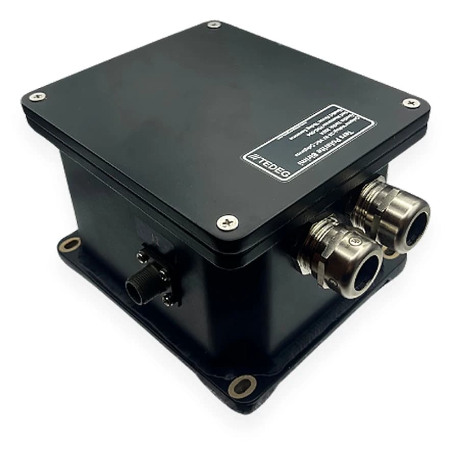
For reverse polarity, the datasheet of TEDEG's PowerGuard TPB-01 Reverse Polarity Unit gives: 12 V / 24 V DC operation, current capacity up to 500 A, internal diode technology that breaks the circuit within milliseconds on reverse polarity, and a time control that shuts the alternator off 8 seconds after the excite signal drops. The enclosure is rated IP67 and designed for −40 °C … +120 °C, a range that matters when the unit sits in a hot location such as the engine bay or battery box.
The battery isolator and emergency stop are usually built into the distribution unit. On the TDG-EDP-D0X described below, both are on the panel; pressing the emergency stop disconnects the input and the load contactor.
3. Distribution Layer: Busbar, Fuses and the Power Distribution Unit
The distribution layer is the physical centre of the architecture, where three design questions are answered:
- 1.How many sources, and on one busbar? Wiring battery 1, battery 2, the alternator and the charger separately gives each its own protection and cable route. One (+) and one (−) busbar shrink the harness and concentrate the protection logic at a single point.
- 2.How are the outputs protected? Every output line should have its own fuse selected for the load current, so a short circuit drops only that line while the mission computer, communications and cameras keep running.
- 3.When are the sources connected? Contactors operating on voltage thresholds protect the batteries from deep discharge and connect the loads only within a safe voltage window.
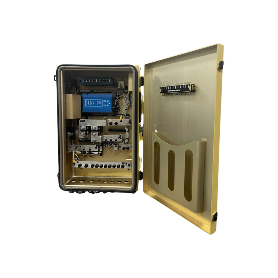
TEDEG's TDG-EDP-D0X Military Vehicle DC Power Distribution Unit answers them with these datasheet values:
- Inputs: 4; Battery 1, Battery 2, the alternator and the battery charger.
- Busbar: (+) and (−), 400 A.
- Output fuses: MIDI type; 30, 60 and 100 A @28 VDC. Three spare MIDI fuses in each of the 30, 60, 100 and 200 A ratings are kept inside the unit.
- Contactor logic: The input contactor closes above 21.5 VDC and opens below 21 VDC, disconnecting the batteries and the load contactor. The control unit switches on when the vehicle battery rises above 11.5 VDC or 21 VDC. Its switch-on voltages are fixed; all other thresholds are adjustable, and a bypass switch inside the panel can override them.
- Enclosure and environment: 5000-series aluminium, watertight to the MIL-STD-810G Method 506.5 Procedure I rain test (30 minutes), IP67 PG cable glands and an EMI gasket on the cover. Two thermostat-controlled axial fans; operating temperature −32 °C … +52 °C; weight 14 ± 2 kg.
Adjustable thresholds let the same unit be adapted to different battery chemistries and vehicle architectures, and spare fuses inside the unit simplify field maintenance. Busbar cross-section, fuse curves and cable sizing will be covered in a separate DC busbar article in this cluster.
The differences between rack-mount PDUs, outdoor panels and vehicle DC distribution units, and automatic transfer switching (ATS), are explained in our military PDU guide; all distribution products are listed under Power Distribution Units (PDU).
4. Conversion Layer: Moving Between 12, 24 and 28 VDC, and Isolation
A vehicle has more than one voltage level: some sources deliver 12 VDC, some loads want regulated 24 VDC, cameras run on 12 VDC. The conversion layer adapts these levels and isolates critical loads from bus transients. Three examples:
- 12 → 28 VDC inside the distribution unit: The built-in converter of the TDG-EDP-D0X turns incoming 12 VDC power into 28 VDC for the bus; it is rated 500 W, starts above 12.5 VDC and stops below 12 VDC.
- Stand-alone DC-DC converter: The PowerGuard-D1000 Mil-Spec DC-DC Converter produces a regulated 24 VDC / 1 kW continuous output from a nominal 12 VDC (10–18 VDC) input, with reverse polarity protection and a user-replaceable 100 A fast-acting fuse on its input.
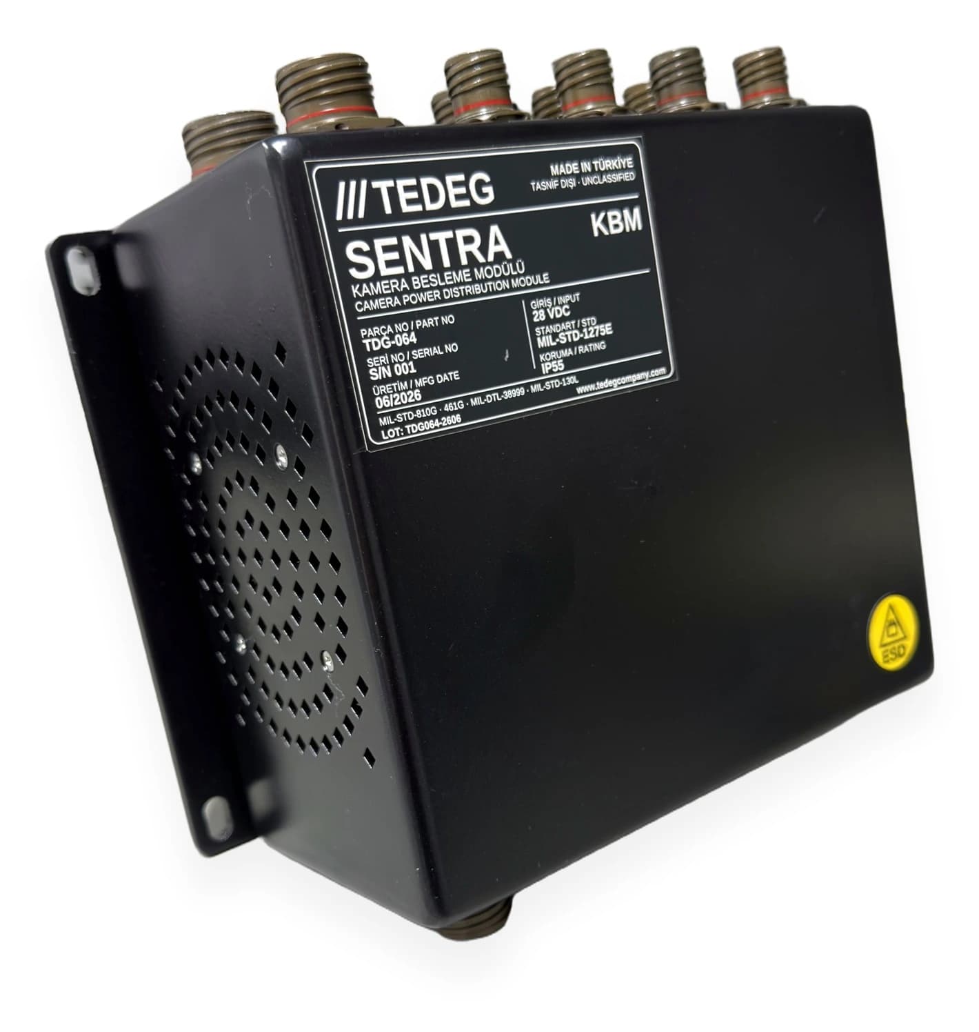
- Isolated sub-distribution: Feeding many small loads such as a vision package individually from the busbar inflates the harness. SENTRA KBM Military Camera Power Distribution Module takes a MIL-STD-1275E compliant 28 VDC input and provides at least 11 isolated 12 VDC camera outputs, 24 VDC ±0.2 V at a minimum of 200 W for the mission computer and an isolated 24 VDC output of at least 25 W for the display. The input has reverse polarity protection and galvanic isolation; on the EMI/EMC side, MIL-STD-461G CE102, CS101/114/115/116, RE102 and RS103 tests are specified.
The architectural value of galvanic isolation: an isolated output does not pass bus surges and spikes straight through to the load, and a short circuit on one camera does not drop the others. Other vehicle electronics are listed under Vetronics (Vehicle Electronics).
5. Load Layer and the Power Budget
The last layer is the loads, and the work here is a power budget built in three columns:
| Column | What is calculated | What it determines |
|---|---|---|
| Continuous power | Sum of all loads in normal operation | Alternator rating, busbar cross-section, main cable |
| Peak power | Coincidence of momentary loads such as turret drive, searchlight, heater | Fuse curves, contactor current, voltage drop |
| Engine-off power | Sum and duration of the loads that must run during silent watch | Battery capacity, APU or backup power unit selection |
The budget should contain priorities as well as totals: as battery voltage falls, which loads are shed first and which stay on to the last? That prioritisation reaches the hardware through contactor thresholds and output grouping.
Monitoring and Diagnostics
In a modern architecture the state of the bus is measured and logged. On the vehicle DC side this starts with contactor thresholds and source status. Platforms fed by a generator or carrying AC loads (mobile command posts, radar vehicles, shelters) also need phase voltage monitoring. According to its datasheet, TEDEG's PowerGuard Voltage Measurement Unit measures up to 21 phases (7 groups × 3 phases) on one board across 0–300 VAC with ±1% accuracy at 50 / 60 Hz, is powered from 220 VAC and sends readings in real time over Ethernet (RJ45); its operating temperature is −32 °C … +55 °C. Such units are listed under Power Management & Protection.
8 Questions When Selecting a Military Power Distribution Unit
- 1.Inputs: How many sources does the unit accept; are batteries, alternator and charger on separate inputs?
- 2.Busbar current: Does the busbar carry peak and starting current as well as the continuous load?
- 3.Output protection: Is every output fused separately; is the fuse type field-replaceable; are spares kept in the unit?
- 4.Contactor logic: Are the input and load contactor thresholds specified and adjustable; is there a bypass?
- 5.Emergency stop and battery isolator: Are both on the panel; which contactors does the emergency stop open?
- 6.Conversion: Is a converter such as 12 → 28 VDC needed inside the unit, and is its rating sufficient?
- 7.Environmental ruggedness: Is the mounting location exposed to rain; to which standard and method is watertightness defined; does the temperature range suit the location?
- 8.Standard references: Does the datasheet state revision and method for MIL-STD-1275, MIL-STD-461 and MIL-STD-810, or only say "compliant"?
The last question matters most. "Designed to comply" and "tested" are not the same thing; which is required and which is offered should be settled at the quotation stage. The MIL-STD guide explains how to verify this.
Military Power Distribution Unit Manufacturer in Turkey: TEDEG Defence
TEDEG Defence is an Ankara-based defence manufacturer that designs and builds products for the distribution, protection, conversion and monitoring layers of the 28 VDC architecture of military land vehicles.
| Company profile | Details |
|---|---|
| Company | TEDEG Defence Industry A.Ş. |
| Headquarters | Ankara |
| Founded | 2023 |
| Registrations and certificates | NCAGE TM885, ISO 9001, EYDEP |
| Cluster memberships | OSSA, SAHA İstanbul |
Vehicle architecture products in this article:
- Distribution: TDG-EDP-D0X DC Power Distribution Unit; 4 inputs, 400 A busbar, MIDI-fused outputs, 12 → 28 VDC 500 W converter.
- Protection: PowerGuard TPB-01 Reverse Polarity Unit; 12 / 24 V DC, up to 500 A, IP67, 8-second alternator shut-off.
- Conversion and isolated distribution: SENTRA KBM Camera Power Distribution Module; MIL-STD-1275E compliant 28 VDC input, at least 11 isolated 12 VDC camera outputs.
- Monitoring: PowerGuard Voltage Measurement Unit; up to 21 phases, 0–300 VAC, Ethernet.
See Certifications & Quality for documents and the product catalogue for the full range.
Frequently Asked Questions
What is the difference between MIL-STD-1275E and MIL-STD-1275D?
Both characterise the 28 VDC bus of military land vehicles; revision E is current, and some of its transient limits and definitions differ from D. Equipment should be assessed against the revision the project specification cites, never against the other.
What is the difference between a vehicle DC power distribution unit and a rack-mount PDU?
A vehicle DC distribution unit collects batteries and alternator on a high-current busbar and splits the 28 VDC loads into fused lines. A rack-mount PDU accepts AC sources such as 220 VAC in a shelter or cabin and usually adds automatic transfer switching and Ethernet monitoring. Both can exist on one platform: a DC unit on the vehicle side, a rack PDU in the mission cabin.
Is the system 24 V or 28 V?
Both. The battery group is nominally 24 V; under alternator charging the bus typically runs at around 28 V, which is why standards and datasheets call it "28 VDC".
Is a separate fuse on every output really necessary?
Yes. A single main fuse leaves the whole vehicle without power when one line short-circuits; a fuse per output confines the fault to that line. The rating follows the line's cable cross-section and the load current.
Can the battery be disconnected while the alternator is running?
Suddenly disconnecting the battery while the alternator runs produces a high-amplitude surge on the bus and stresses the connected equipment. The battery isolator is therefore meant for use with the engine off; the contactor logic connects and disconnects the batteries in a controlled way according to voltage thresholds.
Conclusion
Military vehicle electrical architecture is the joint design of five layers: sources, protection, distribution, conversion and loads. MIL-STD-1275 is their common language; how a product in each layer behaves under the surges, spikes and starting dips of the bus is read against it. The inputs, busbar current, fuse arrangement and contactor thresholds of the distribution unit determine how much maintenance the architecture will need in the field.
For a distribution and protection architecture that fits your vehicle's battery, alternator and load layout, request a quote or contact our engineering team.
Field example: Read the tactical truck power architecture modernisation case study, in which the distribution, protection and monitoring layers were renewed together.