Where Does Mil-Spec DC-DC Converter Selection Start?
A vehicle never has just one voltage: the bus may be 12 V or 24/28 V, while the radio wants 28 V, the mission computer regulated 24 V and the camera 12 V. The bridge is the mil-spec DC-DC converter, and a wrong choice usually shows up on the first field trial: a computer that resets during cold crank, a module that derates in the heat, a failed MIL-STD-461 limit.
This guide sets out eight criteria for selecting a military DC-DC converter and the datasheet line to read for each. If your source is mains or a generator, start with our article on mil-spec AC-DC converters versus commercial power supplies. Examples come from our AC-DC and DC-DC power converters category.
1. Input Voltage Range: Bus Behaviour, Not the Nominal Value
"12 VDC nominal" says little; what matters is the bus at its worst: voltage collapses during cranking, rises on load dump and drops along long cables. Read three values together:
- Operating range: between which limits is full power delivered?
- Undervoltage lockout (UVLO): where does it shut down, with hysteresis? Without it, a bus hovering at the threshold cycles the output.
- Transient protection: to which profile is it specified?
The PowerGuard-D1000 states them plainly: 10–18 VDC input (12 VDC nominal), UVLO at 8.5–9.5 V with hysteresis, built-in cold-crank and transient protection, and compatibility with a 12 V military vehicle bus to the ISO 7637-2 profile. On 24 V vehicles, the TPS-24DCAC runs from a wide 16–28 VDC input.
On 28 VDC military ground vehicles, bus behaviour is defined by MIL-STD-1275; its ripple, spike and surge concepts are covered in our military vehicle electrical architecture guide. Specify the revision and operating mode; "28 V compatible" does not cover it.
2. Isolation: When You Need It and How to Read It
An isolated DC-DC converter has no galvanic link between input and output: it breaks ground loops, cuts the bus noise reaching the load and stops output faults travelling back to the bus. On lines feeding many cameras or sensitive sensors, isolation is usually a requirement; see how to power armoured vehicle cameras.
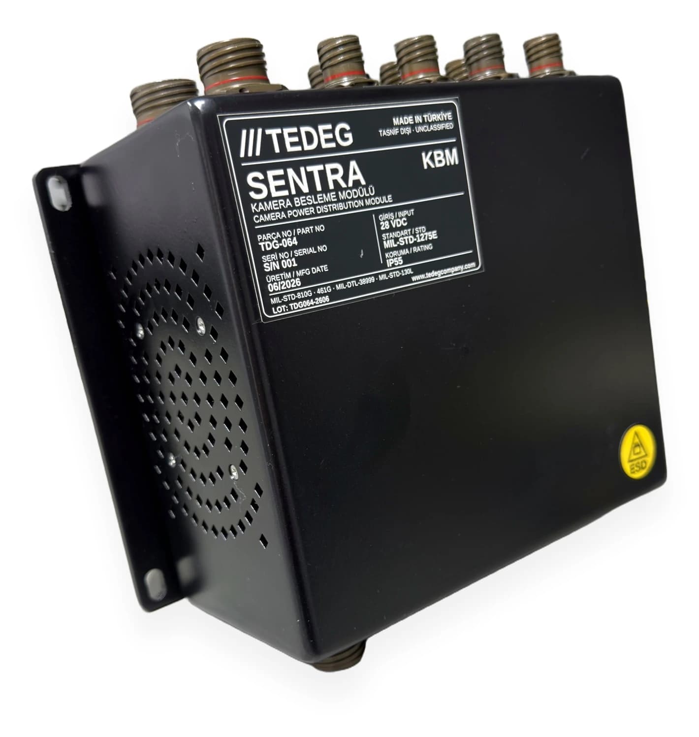
Check two things. First, the isolation rating and how it is verified: on the D1000, input–output isolation is 1500 VDC, 1-minute factory test. Second, where the return goes: on the TPS-24DCAC all outputs are isolated from the input and from each other, and each DC return is independent and not bonded to the chassis. For cameras, SENTRA KBM applies the same idea at sub-distribution level: at least 11 isolated 12 VDC camera outputs from a MIL-STD-1275E compliant 28 VDC input.
3. Efficiency, Heat and Cooling
Efficiency is a heat budget: lost power becomes heat inside a closed box.
Worked example
In general numbers: 1000 W out at 90% efficiency means about 1111 W in and about 111 W of heat; at 80% it means 1250 W in and 250 W of heat, more than twice the loss. Input current scales inversely with voltage: a 500 W, 90% unit drawing about 20 A at 28 V draws about 35 A at 16 V. Size cables, fuses and connectors for the lowest operating voltage.
On the D1000, efficiency is ≥ 90% (12 V input, full load) and input current at full load is up to 95 A, with a 100 A fast-acting, user-replaceable input fuse. On the multi-output TPS-24DCAC, DC-DC efficiency is given as 80% typical.
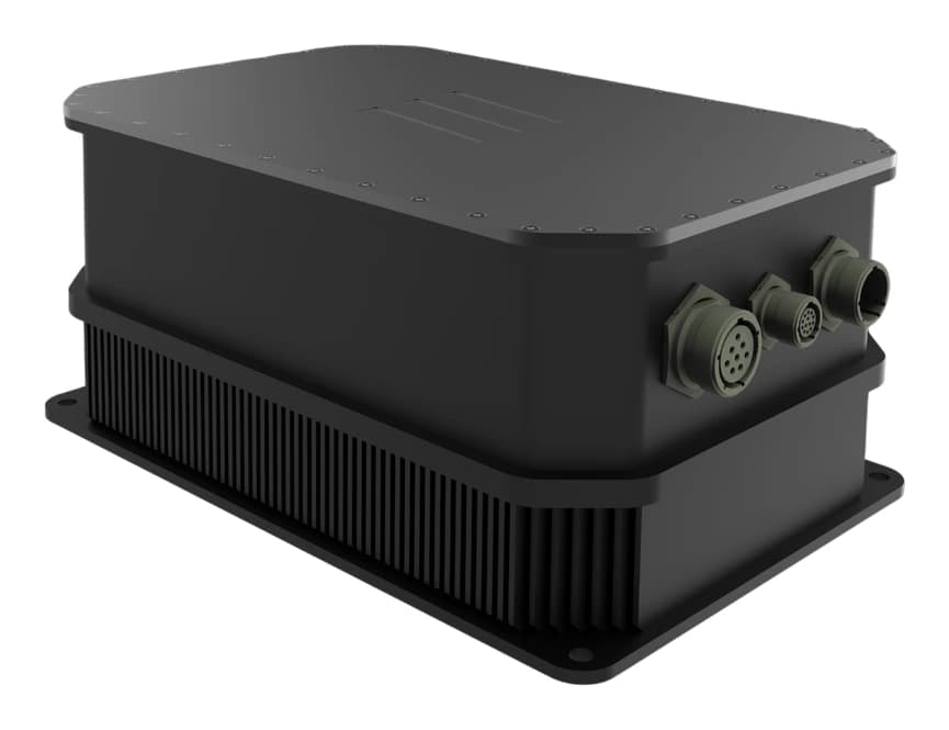
The fanless, conduction-cooled D1000 passes heat through its baseplate into the frame or a heatsink and delivers 1000 W without derating up to +55 °C (operating range −32 °C to +55 °C). The TPS-24DCAC uses 4 fans; it runs at 100% load from −20 °C to +40 °C, and at +60 °C its DC-DC modules run continuously at 70%. Compare the derating curve with the real installation temperature.
4. Output Quality: Regulation, Ripple, Hold-Up
Read the output lines against what the load needs:
- Regulation: D1000: ±1% typ., ±2% max. over input and load; output 23.8–24.5 V.
- Ripple and noise: read with the bandwidth; D1000: 200 mVp-p max. (20 MHz BW).
- Transient response: D1000: recovery < 2 ms for a 50% load step.
- Hold-up time: D1000: 5 ms typ., external bulk capacitance optional.
- Start-up delay: for power-up sequencing; D1000: 500 ms typ., 1000 ms max.
If hold-up cannot ride a computer through cold crank, add external capacitance or system-level backup power.
5. EMI Filtering and MIL-STD-461
Switching noise lands on the bus feeding radios and sensors, so filtering belongs in the design from day one. The D1000 has integrated differential- and common-mode EMI filters plus surge protection from TVS diodes and an LC damping network; its datasheet cites MIL-STD-461 (conducted and radiated emissions) for EMC and MIL-STD-810G as the environmental standard.
Two distinctions matter. First, revision and test list: naming MIL-STD-461G tests one by one, as the SENTRA KBM datasheet does with CE102, CS101/114/115/116, RE102 and RS103, says far more than "MIL-STD-461". Second, evidence level: "designed to comply" and "test report available" differ; if you need a report, say so in the RFQ. We explain the test methods in our MIL-STD-461 and MIL-STD-810 guide.
6. Protection, Monitoring and the Vehicle Network
The D1000 carries overvoltage, overcurrent, short-circuit, overtemperature and reverse polarity protection; what matters is whether the system can see them. On the D1000, an opto-isolated ON/OFF pin and a Power Good signal (active while the output is in regulation) are standard; optional CAN-Bus (ISO 11898 / J1939), RS-485 (Modbus/RTU) or Ethernet interfaces add remote monitoring, fault reporting and firmware updates.
7. Parallel and Redundant Operation
If one failure would stop the mission, consider paralleling (needs current sharing) or N+1 redundancy (outputs separated by diodes or ideal-diode circuits). If the datasheet does not specify parallel operation, do not tie outputs together; ask the manufacturer or feed the critical load from a separate converter.
8. Connectors, Cabling and Mounting
On the D1000, power input and output use MIL-DTL-38999 Series III connectors (D38999/24WE6PN and D38999/24WE6SN, 12 AWG); keying prevents mismating, and the connectors provide 360° EMI shielding and sealing. The baseplate-to-chassis contact is both heat path and bonding path. For busbar, fuse and cable sizing, see our DC busbar guide.
10 Lines to Write into Your Specification
| # | Line | Why |
|---|---|---|
| 1 | Bus type, operating range, standard revision | Nominal hides the worst case |
| 2 | UVLO threshold and hysteresis | No cycling during cranking |
| 3 | Isolation rating and test condition | Grounding and safety |
| 4 | Chassis connection of the return line | Ground-loop risk |
| 5 | Efficiency and its conditions | Heat and input current |
| 6 | Derating curve and cooling method | Real installation temperature |
| 7 | Regulation, ripple (with bandwidth), hold-up | What the load needs |
| 8 | MIL-STD-461 revision, test list, evidence level | "Designed to comply" vs "tested" |
| 9 | Protection, Power Good, remote control, comms | System visibility |
| 10 | Connector, cable cross-section, mounting, fuse | Current at lowest voltage |
Mil-Spec DC-DC Converter Manufacturer in Turkey: TEDEG Defence
| Company profile | |
|---|---|
| Company | TEDEG Defence Industry A.Ş. |
| Location | Ankara, Turkey |
| Founded | 2023 |
| Registrations and certificates | NCAGE TM885, ISO 9001, EYDEP |
| Cluster memberships | OSSA, SAHA Istanbul |
- PowerGuard-D1000: 10–18 VDC input; regulated 24 VDC / 1000 W continuous; efficiency ≥ 90%; 1500 VDC isolation; fanless, conduction-cooled; no derating up to +55 °C; MIL-DTL-38999 Series III.
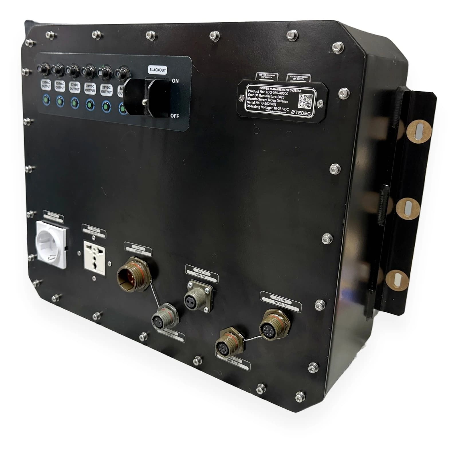
- TPS-24DCAC: 16–28 VDC input; isolated 12, 24, 28 and 36 VDC outputs (10 A each) plus 120/220 VAC pure sine outputs in one panel.
- SENTRA KBM: at least 11 isolated 12 VDC camera outputs from a MIL-STD-1275E compliant 28 VDC input.
For 24 VDC from AC, the PowerGuard-A1000 delivers 24 VDC / 1 kW from a single-phase 45–420 Hz input. See also Certifications and Quality and the product catalogue.
Frequently Asked Questions
What is the difference between an isolated and a non-isolated DC-DC converter?
An isolated converter has no galvanic link between input and output, so it breaks ground loops and cuts bus noise at the load. A non-isolated one can be smaller and more efficient, but input and output share a return. Multi-channel sensitive loads favour isolation.
How do you run 24 V equipment on a 12 V vehicle?
Use a step-up DC-DC converter. The PowerGuard-D1000 produces regulated 24 VDC / 1 kW from a nominal 12 VDC (10–18 VDC) input; input current reaches 95 A at full load, so size cabling accordingly.
Why does efficiency matter so much in a DC-DC converter?
At 1 kW output, 90% efficiency means about 111 W of heat and 80% means 250 W; that drives cooling and enclosure size.
How do you verify a MIL-STD-461 compliant DC-DC converter?
Check the revision and the tests specified (such as CE102, CS101, CS114, RE102, RS103). "Designed to comply" and a test report are different evidence levels; state any report requirement in your RFQ.
Conclusion
Mil-spec DC-DC converter selection starts with the bus at its worst, not with nominal voltage: input range and UVLO, isolation and return, efficiency as heat, output quality, MIL-STD-461 evidence, protection, redundancy and connectors. Put the ten lines above into your specification and compare quotes on the same scale.
Send your bus voltage, output voltage and power, ambient temperature and test report requirement via the quote form, or contact our engineering team.