What Is MIL-STD-1275?
MIL-STD-1275 is the US military standard that defines the characteristics of the 28 VDC electrical system in military ground vehicles. In short, it describes the voltage, ripple and transients the vehicle network may deliver to equipment's power input, and how much disturbance that equipment may push back, giving vehicle and equipment designers one shared set of limits.
This article covers the standard itself: scope, revisions, operating modes, disturbance types and how to read it on a datasheet. Its place in the wider vehicle design is covered in our military vehicle electrical architecture guide. A short definition is also in the glossary.
Scope: What Does the Standard Define, and Where?
MIL-STD-1275 is explicit about the measurement point: the equipment's power input terminal, not the battery post or alternator output. A long, thin cable adds steady-state voltage drop and, through its inductance, reshapes transients on the way.
The standard places obligations on both sides:
- Vehicle side (design authority): keeps the 28 VDC delivered to equipment within the defined limits. Batteries, alternator, regulator, busbar and harness are chosen with that target in mind.
- Equipment side: delivers its specified performance across the whole defined range, survives the transients, and does not inject more ripple or spikes onto the network than allowed.
The scope is nominal 28 VDC ground-vehicle systems. Naval networks are defined by other standards, and 12 V civilian vehicle electronics are outside this one.
Revisions: From 1275A to 1275F
The first edition was MIL-STD-1275A (1976). Later revisions refined the transient definitions, the test methods and the operating modes. The reference most often seen in the field today is MIL-STD-1275E (2013); standards listings also carry MIL-STD-1275F, dated September 2022.
Equipment is assessed against whichever revision the platform specification cites; some limits, durations and test set-ups changed between revisions. Most product datasheets still refer to revision E, so if your specification calls up F, ask about it at the quotation stage.
Operating Modes: Normal, Generator-Only and Starting
The same vehicle network behaves very differently depending on whether the battery is connected. Revision E therefore separates its limits by operating mode:
- Normal operating mode: battery and alternator are both on line. The battery acts like a very large capacitor and absorbs transients, so the network is relatively quiet.
- Generator-only mode: the battery has been disconnected or the battery isolator is open. With nothing to absorb them, surges caused by a large load dropping off the alternator are more severe. This is usually the worst case when sizing an equipment input stage.
- Starting: while the starter motor cranks, the bus voltage dips sharply for a short time. Whether equipment must keep running, shut down in a controlled way or restart is set by the platform specification.
When a datasheet says "MIL-STD-1275E", it is worth asking which modes are covered.
Disturbance Types: Steady State, Ripple, Spikes and Surges
The events differ widely in duration and energy. Values below are limited to those consistently reported for revision E; exact values, durations and test waveforms must always be taken from the tables of the revision you are working to.
| Event | What it describes | Typical source | Equipment stage affected |
|---|---|---|---|
| Steady state | Long-term operating voltage; 20–33 VDC including ripple in 1275E | Battery state of charge, regulator setting, cable drop | Input range, current and heat at low voltage |
| Ripple | AC component riding on the DC voltage | Alternator rectifier, switching loads | Input filter, output quality |
| Spike | Microsecond-scale, very high amplitude pulse; ±250 V for about 70 µs in 1275E | Switching of inductive loads such as relays, contactors and motors | Transient voltage suppressor, input capacitors |
| Surge | Lower amplitude but high-energy event lasting milliseconds to hundreds of milliseconds | Sudden load dump on the alternator (especially in generator-only mode) | Input protection topology, over-voltage cut-off |
| Starting dip | Brief voltage drop during engine cranking | Starter motor current | Hold-up time, under-voltage behaviour |
A surge is defined by amplitude, duration and source impedance together: the same peak voltage from a low-impedance source dumps far more energy into a protection device.
Injected Versus Emitted
The standard works in two directions. The equipment must withstand injected ripple, spikes and surges, and must limit the emitted ripple and spikes it puts back on the network so that other equipment on the same bus is not disturbed. A strong input suppressor addresses the first; the second depends on filtering and switching design. This emission side also overlaps with MIL-STD-461 through conducted emissions; we explain how the two standards relate in our MIL-STD-461 and MIL-STD-810 guide.
Reverse Polarity
Reversing the battery terminals during a battery change or a jump start is a separate failure mode, and current revisions expect equipment to withstand it. Voltage level and duration should be read from the revision. Protection options on the battery line and at the device input are covered in our reverse polarity guide.
MIL-STD-1275 Versus Civilian Vehicle Standards
Commercial truck and automotive electronics are usually assessed against standards such as ISO 7637-2 (conducted transients) and ISO 16750-2 (electrical loads). These also define load dump, starting and pulse events, but their waveforms, levels and operating modes do not map one-to-one onto the military 28 VDC network. A product designed to an ISO 7637-2 profile is not automatically MIL-STD-1275 compliant, and the reverse is also true.
In the United Kingdom, DEF STAN 61-5 Part 6 plays a similar role for land vehicles; on export programmes, settle early which national standard applies. We show how civilian and military input profiles affect converter selection in our mil-spec DC-DC converter selection guide.
How to Read MIL-STD-1275 on a Datasheet
"MIL-STD-1275" on a datasheet can describe different levels of evidence. Look for answers to these questions:
- 1.Is there a revision letter? "MIL-STD-1275" on its own is not enough; D, E or F should be stated.
- 2.What is the verb? "Designed to", "referenced protection" and "tested" are different claims. If testing is claimed, ask for the report and the laboratory.
- 3.What is the input range? Does the declared continuous input range cover the steady-state range?
- 4.Which events are listed? Are ripple, spikes, surges, starting and reverse polarity named separately?
- 5.Which modes? Is generator-only mode covered?
Three TEDEG products show how these questions are answered:
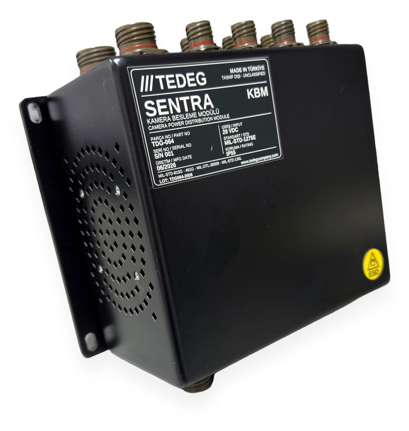
- The datasheet of the military camera power distribution module SENTRA KBM describes its input as MIL-STD-1275E compliant 28 VDC and lists reverse polarity protection and galvanic isolation separately. How camera lines are fed from that input is covered in our armoured vehicle camera power guide.
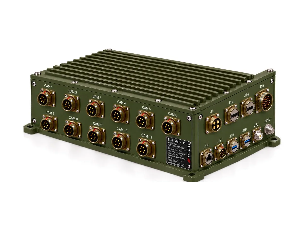
- The military vehicle video management system TDG-VMS-111 specifies an 18–33 VDC (28 VDC nominal) input with reverse-polarity, over-voltage and surge protection, and MIL-STD-1275E power quality (ripple, spikes, surges and voltage dips). The datasheet gives these as Rev. 01 preliminary design values.
- On the 28 VDC solid-state rack PDU PowerGuard DC-PDCU-11, input protection is MIL-STD-1275E referenced: reverse polarity, over-voltage, spikes and surges.
Battery-line protection is a separate layer. The 500 A reverse polarity protection unit PowerGuard TPB-01 works on 12 V / 24 V DC battery systems at up to 500 A in an IP67 enclosure; its datasheet makes no MIL-STD-1275 claim; its role is to break a wrong connection at the head of the line. See also the military power management and protection and military power distribution units pages, including the vehicle DC power distribution unit TDG-EDP-D0X.
Writing a MIL-STD-1275 Clause Into a Specification
"Shall comply with MIL-STD-1275" alone invites different readings at the quotation stage. A clearer clause covers:
- Revision: "MIL-STD-1275E" or "MIL-STD-1275F", whichever the platform power system was designed to.
- Modes: expected behaviour in normal, generator-only and starting modes (keep running, controlled shutdown, automatic restart).
- Event list: steady state, ripple, spikes, surges, starting dip and reverse polarity as separate lines.
- Level of evidence: design declaration or qualification test; if testing is required, what the report must contain.
- Emission limit: that ripple and spikes emitted onto the network are also covered.
For power distribution units specifically, we collected how these clauses sit alongside the other requirements in a 12-point list in our military PDU specification guide.
Frequently Asked Questions
What is the latest revision of MIL-STD-1275?
Standards listings carry MIL-STD-1275F, dated September 2022; datasheets most often cite MIL-STD-1275E from 2013. Your programme specification decides which applies.
Does MIL-STD-1275 apply to 24 V systems?
It defines the nominal 28 VDC network, which in practice is a 24 V battery set charged by the alternator, so most military "24 V vehicles" fall under it. 12 V systems are out of scope.
Is MIL-STD-1275 the same as MIL-STD-461?
No. MIL-STD-1275 defines the voltage characteristics and transients at the power input. MIL-STD-461 covers electromagnetic emissions and susceptibility, conducted and radiated. The two overlap on conducted emissions and are usually required together.
Does "MIL-STD-1275 compliant" mean tested?
Not always. "Compliant" or "referenced" describes the design target; a test claim is stated separately and backed by a report. If you need qualification testing, say so in the request for quotation.
Conclusion
MIL-STD-1275 is the common language of the power input on a 28 VDC military ground vehicle. Using it well means reading the revision letter, the operating modes and the level of evidence together. For a field example on a tactical vehicle, see our case study.
Send your 28 VDC power distribution, protection or vehicle electronics requirement through our quote form, or reach the engineering team via the contact page.